DIY Guitar Vocoder Pedal Using BWE-VO3 Module and GBPM-2 PCB
WARNING! As of August 30th 2023, BWE-VO3 module is discontinued (obsolete), replaced by DT-VO4 vocoder module. Refer to the following documents to build DT-VO4 Vocoder:
- DT-VO4 Vocoder Module User Manual
- DT-VO4 Application Note (BUILDING GUITAR VOCODER PEDAL USING DT-VO4 MODULE AND BGPM-2 PCB)
Introduction
BWE-VO3 is a vocoder effect module designed for guitar effect pedal application, based on digital simulation of analog channel vocoder (https://www.deeptronic.com/manual/bwe-vo3-vocoder-module-user-manual/)
Here are the main features of this vocoder:
- 18-channel filters on both analyzer and synthesizer
- Triple operation modes: talkbox, classic, and unison
- Gender control for classic mode
- Resonance frequency control for talkbox mode
- Unison width control for unison mode
- Knob’s center-position calibration
- Configurable microphone gain range and noise gate level for wide variety of dynamic microphone pickups
The physical size and the electrical interface specification of BWE-VO3 module follows the BLACKSTOMP-CORE (BSCORE) module open standard (https://www.deeptronic.com/blackstomp/i-blackstomp-hardware/), so it is possible to build a vocoder pedal using the module with the BGPM-2 PCB (BSCORE generic production model-2), which is one of the generic PCB versions designed for BSCORE module. As the BGPM-2 PCB is licensed for everyone to use in any type of products (including commercial one), it could be the cheapest option to build the BWE-VO3 vocoder because we don’t need to design a specific PCB for this.
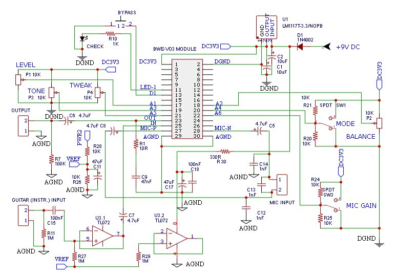
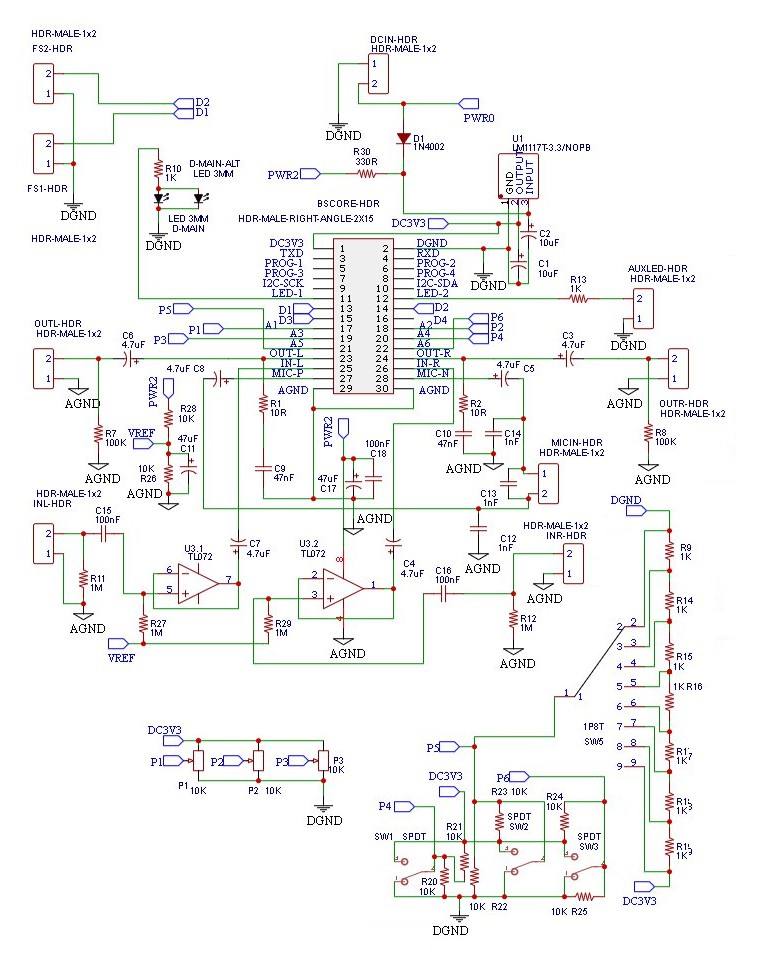
Schematic Diagram of BWE-VO3 Vocoder and BGPM-2 Circuits
Figure 1 shows the schematic diagram of typical BWE-VO3 vocoder circuit. Compared to the BGPM-2 circuit shown in the Figure 2, the vocoder circuit has less components since it uses only the left channel and doesn’t need the 1P8T rotary selector switch.
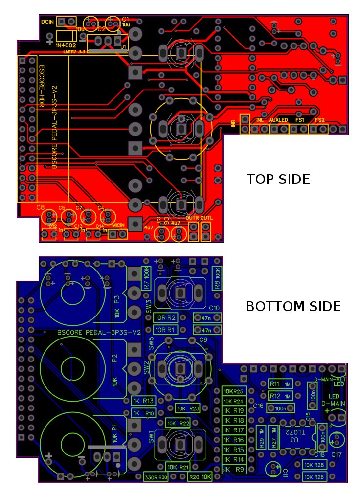
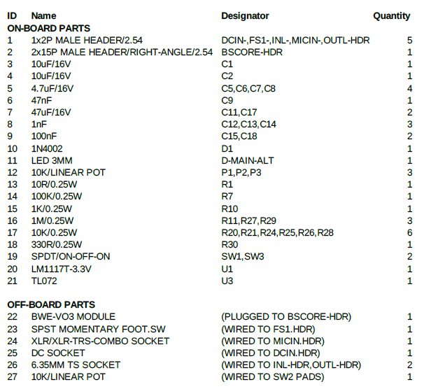
BGPM-2 PCB and The Bill of Materials (BOM)
The BGPM-2 PCB is shown in Figure 3, and the BOM in the Table 1. The PCB’s gerber file is available to download at https://github.com/hamuro80/blackstomp/blob/master/hardware/Gerber_PCB_BGPM_2_V2.zip
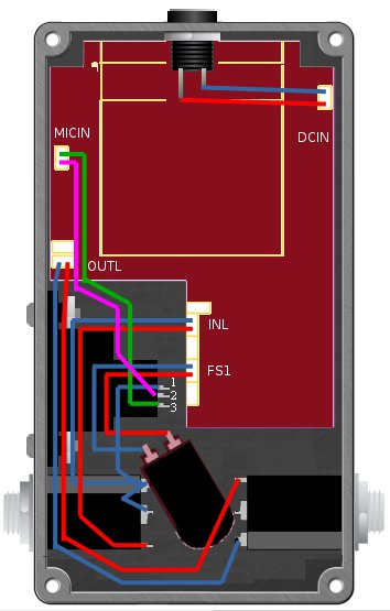
It is clear that in order to use BGPM-2 PCB for building BWE-VO3 vocoder, we just need to populate the vocoder circuit’s components only, and leave the unused component pads in the PCB blank. Also note that the P4 potentiometer has no mounting pads on the board so we have to wire it off-board to the available SW2 switch pads. Refer to Figure 6 for the off-board components wiring.
Buy BWE-VO3 Module Buy BGPM-2 PCB
Drill Template
BGPM-2 is designed for 125B enclosure size, and the printable drill template is shown in the Figure 4. Make sure the printed template’s actual size fits into the actual pedal enclosure. Note that he hole for the microphone input socket has 2 optional diameter size (22/24 mm), and doesn’t include the mounting screw hole marks. Make sure you have the actual socket before drilling to choose the right diameter to drill. You can print it from the following printable document: https://www.deeptronic.com/wp-content/uploads/2022/06/DRILL-TEMPLATE-125B.pdf
Printable Enclosure Label
A printable label for 125B enclosure is shown in the Figure 5. It can be printed as a sticker or directly printed to the enclosure using UV printer. You can print it from the following printable document: https://www.deeptronic.com/wp-content/uploads/2022/06/PRINTABLE-LABEL-125B.pdf
Off-Board Components Wiring
Controls
- BYPASS switch is used to activate/deactivate the effect by un-bypass and bypass. In tap menu operation, this switch is used to do a single-tap or multi-tap command (see sections VIII and IX)
- LEVEL knob controls the output level in normal operation, and controls the microphone gain adjustment in the microphone calibration menu
- BALANCE knob controls the proportion of dry-wet signal mix in normal operation, and controls the microphone’s noise gate level in the microphone calibration menu (see section VIII)
- TONE knob controls the tone of the vocoded signal
- TWEAK knob controls several different parameters depending on the selected effect mode (determined by MODE switch).
- On talkbox mode, this knob controls the resonance frequency of the talkbox tube
- On classic mode, this knob controls the gender bender
- On unison mode, this knob controls the unison width
- MODE switch controls the selected effect mode (talkbox, classic, or unison)
- MIC GAIN switch controls the microphone gain (low, medium, high)
Microphone Gain and Noise Gate Calibration
With some microphone or in some situations, trying all the microphone gain settings from low, medium, and high might fail to prevent unwanted feedback from the vocoded sound getting back into the microphone. If it happens, we can try to lower the internal gain or adjusting the noise gate setting for the microphone by following these steps:
- Before entering the microphone calibration menu, adjust the LEVEL and BALANCE knobs to the best level to observe the feedback or to judge the sensitivity. The recommended setting for the LEVEL knob is at the center, and all the way up for the BALANCE (100% wet). All other knobs and controls will still be available to manipulate after entering the menu operation, and it is recommended to set them on classic mode with centered tone, centered gender, and medium mic gain.
- Do a multitap of 6-taps on the bypass foot switch. Make sure the period between successive taps is not more than 0.5 seconds to be a “single multitap operation”. A continuous blinking will be shown by the CHECK indicator to indicate that the microphone calibration menu is in operation. Try the multitap again if the indicator doesn’t show this operation state.
- Adjust the LEVEL and BALANCE knob to change the internal gain and the noise gate level of the microphone. Although the control knobs are continuous, their controlled parameters are not: the internal gain has 5-level to adjust, while the noise gate level has 32-level.
- After done with the adjustment, we can exit the microphone calibration operation by one of the following three ways:
- Do a tripple-tap to accept the adjustment and save the setting
- Do a double-tap to cancel the adjustment and apply the default (factory) setting
- Do a single-tap to cancel the adjustment and revert back the previous setting
After exit from this menu operation, the CHECK indicator should stop blinking and turned continuously-ON to indicate the normal operation.
Knob’s Center-Position Calibration
At the first time the module or the pedal is powered-on, or when the potentiometer knob is replaced or readjusted for maintenance, the center position of the knob reading (by the firmware) need to be calibrated. Use the following steps to do the calibration:
- From a normal operation (either bypassed or un-bypassed), do a multitap of 10-taps. Make sure the period between successive taps is not more than 0.5 seconds to be a “single multitap operation”. A repetitive 5-blink will be shown by the CHECK indicator to show that the pedal is in the knob calibration operation. Retry the multitap if the CHECK indicator doesn’t show it.
- Turn all the way down the first knob, then turn to the center position. Do the same for all the knobs one by one.
- Exit the knob calibration operation by one of the following three ways:
- Do a triple-tap to accept the adjustment and save the setting
- Do a double-tap to cancel the adjustment and apply the default (factory) setting
- Do a single-tap to cancel the adjustment and revert back the previous setting
After exit from this menu operation, the CHECK indicator should stop blinking and turned continuously-ON to indicate the normal operation.