I. Blackstomp Hardware
I.1 Blackstomp Core (BSCORE) Module’s Physical Design Specification
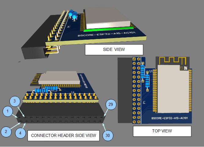
Blackstomp core (BSCORE) module is designed to provide a standardized pinout for the main processing module, so it can be implemented with various type of generic processors which is available on the market. Figure 1 shows the physical design of the module in 2D drawing, and Figure 2 shows it in perspective drawing.
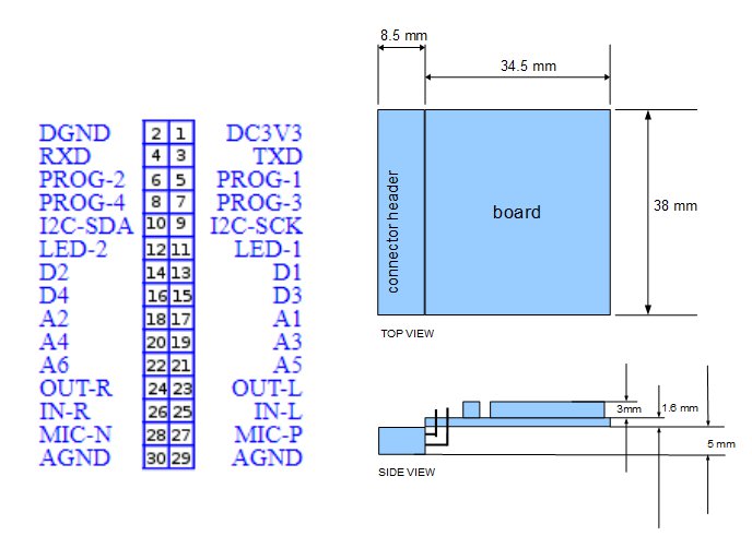
I.2 BSCORE Module’s Pinout Specification
- DC3V3: Power supply input +3.3V, mandatory
- DGND: Power, digital, and analog ground, mandatory
- TXD: UART (universal asynchronous receiver transmitter) data transmitter (3.3V level), mandatory
- RXD: UART (universal asynchronous receiver transmitter) data receiver (3.3V level), mandatory
- PROG1: Platform-agnostic programming pin (depends on the specific implementation), optional
- PROG2: Platform-agnostic programming pin (depends on the specific implementation), optional
- PROG3: Platform-agnostic programming pin (depends on the specific implementation), optional
- PROG4: Platform-agnostic programming pin (depends on the specific implementation), optional
- I2C-SCK: I2C clock (optional)
- I2C-SDA: I2C data (optional)
- LED1: Main indicator LED, mandatory
- LED2: Auxiliary indicator LED, mandatory
- D1: Digital input, mandatory
- D2: Digital input, mandatory
- D3: Digital input, mandatory
- D4: Digital input, optional
- A1: Analog input (0-3.3V), mandatory
- A2: Analog input (0-3.3V), mandatory
- A3: Analog input (0-3.3V), mandatory
- A4: Analog input (0-3.3V), mandatory
- A5: Analog input (0-3.3V), mandatory
- A6: Analog input (0-3.3V), mandatory
- OUT-L: Left output (line-level), mandatory
- OUT-R: Right output (line-level), mandatory
- IN-L: Left input (line-level), mandatory
- IN-R: Right input (line-level), mandatory
- MIC-P: Positive differential microphone input , mandatory
- MIC-N: Negative differential microphone input, mandatory
- AGND: Audio ground
- AGND: Audio ground
I.3 BSCORE Module’s Schematic Diagram
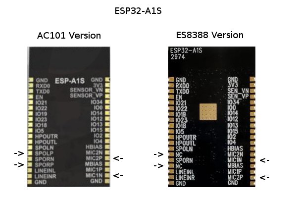
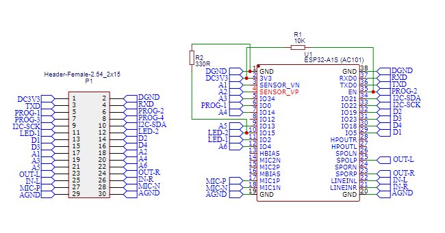
There are currently 2 variations of BSCORE implementation i.e. ESP32-A1S-AC101 version and ESP32-A1S-ES8388 version. We are working on ESP32 Wrover + WM8776 as the next variation for higher fidelity, and will be published here when it done. When working with ESP32-A1S, we have to identify whether it is the AC101 or ES8388 version because it has completely different pinout. Figure 3 show the different pinouts between both versions.
The Main Differences Between ESP32-A1S-AC101 and ESP32-A1S-ES8388 version of BSCORE Module
- Audio codec: ESP32-A1S-AC101: AC101 chip, ESP32-A1S-ES8388: ES8388 chip
- Microphone gain > ESP32-A1S-AC101: (0:0dB,1-7:30dB-48dB), ES8388: (0:0dB,1-8:3dB-24dB)
- I2S interface > ESP32-A1S-AC101: available, ESP32-A1S-8388: not available
- Available digital input > ESP32-A1S-AC101: (D1,D2,D3,D4), ESP32-A1S-8388: (D1,D2,D3)
I.3.1 BSCORE ESP32-A1S-AC101 Module’s Schematic Diagram
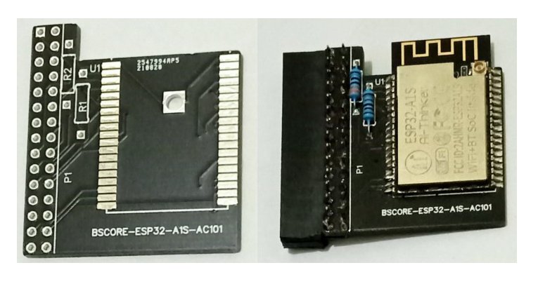
The schematic diagram of ESP32-A1S-AC101 BSCORE module is shown in the Figure 4. The PCB and its assembled module is shown in the Figure 5. There are two options to get the module:
- Download the gerber file here (free, even for commercial use) to fabricate your own PCB and assembly
- Buy the PCB or the assembled module from our store
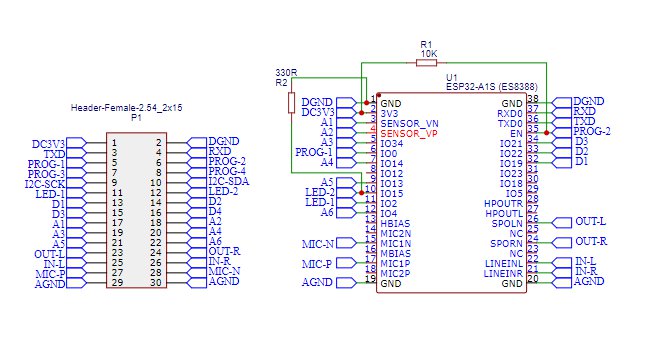
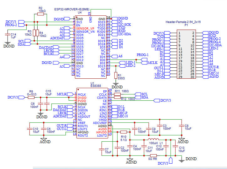
I.3.2 BSCORE ESP32-A1S-ES8388 Module’s Schematic Diagram
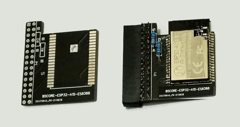
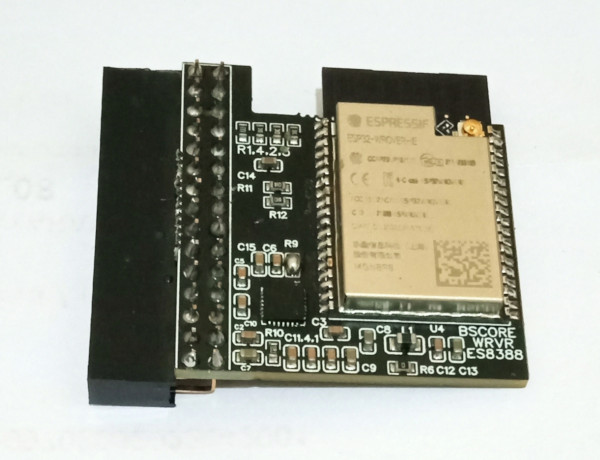
The schematic diagram of ESP32-A1S-ES8388 BSCORE module is shown in the Figure 6. The PCB and its assembled module is shown in the Figure 7. There are two options to get the module:
- Download the gerber file here (free, even for commercial use) to fabricate your own PCB and assembly
- Buy the PCB or the assembled module from our store
I.3.3 BSCORE WROVER-ES8388 Module’s Schematic Diagram
The schematic diagram of the BSCORE-WROVER-ES8388 is shown in the Figure 7.2, and the assembled module is shown in the Figure 7.3. To get this BSCORE module:
- Design your own PCB based on the circuit’s schematic (Figure 7.2) and fabricate the PCB and the assembly.
- Buy one pcs of BSCORE-WROVER-ES8388 module from Deeptronic’s Store and get the complete fabrication files (Gerber files, pick and place files, etc.) as the bonus, so you can use use it for your own mass production later.
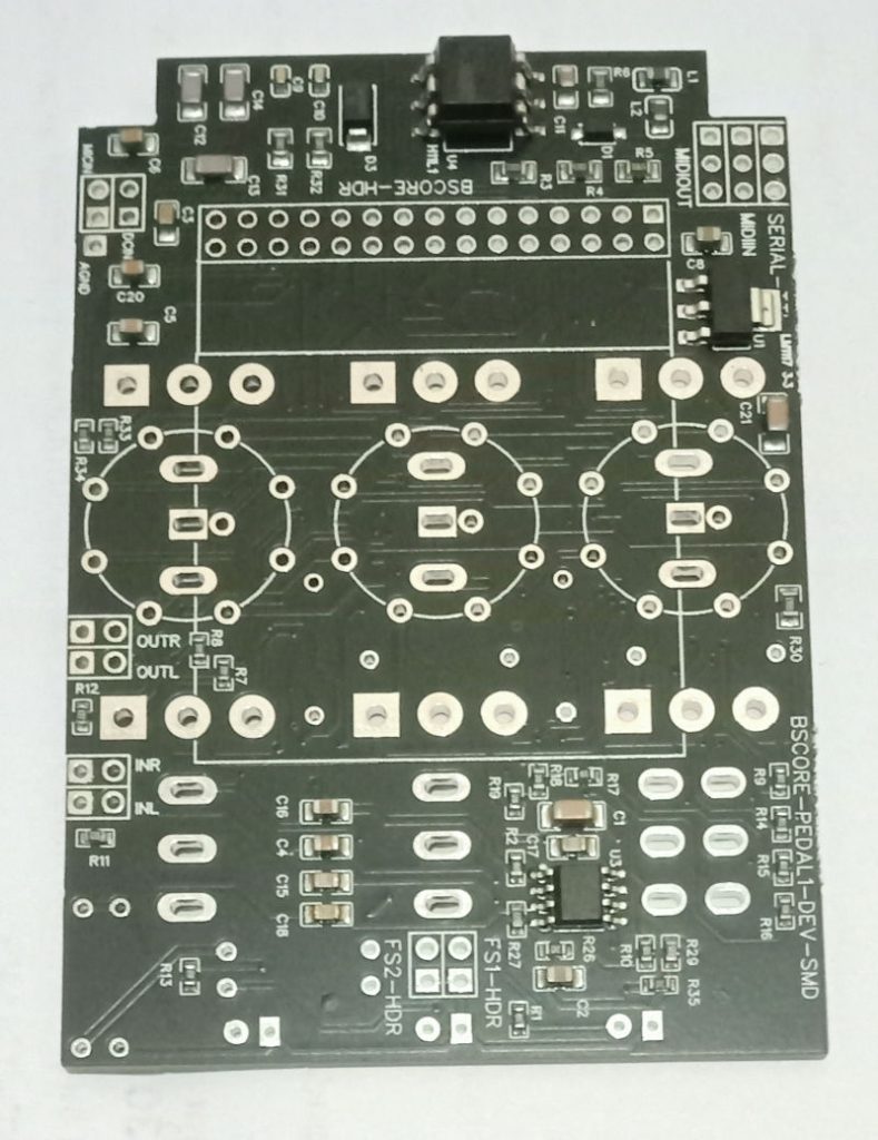
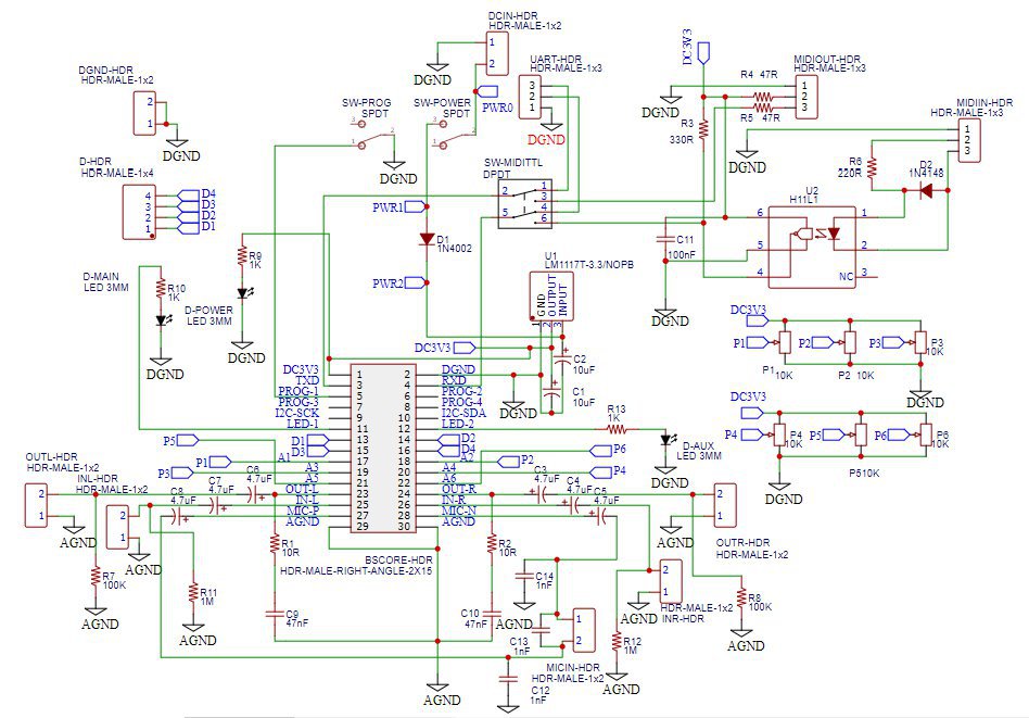
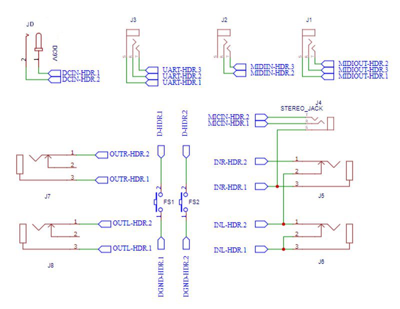
I.4 BSCORE Development Mode Pedal Circuit Schematic Diagram
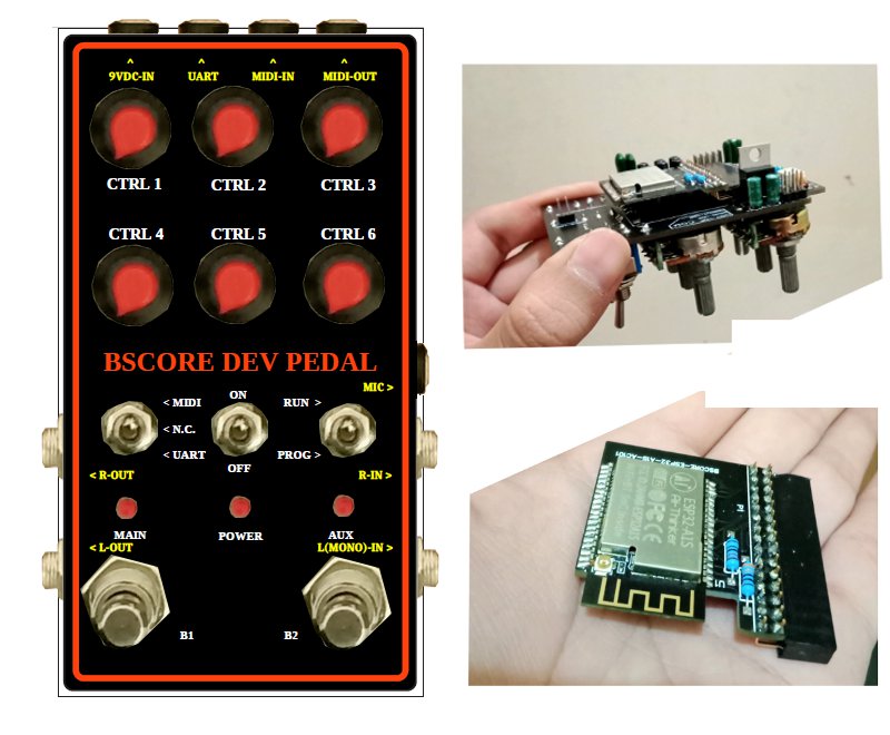
Development mode pedal enable convenient firmware reprogramming to speed up your new effect development and testing cycles. The pedal is designed to fit in 125B enclosure (Figure 11-Left), with the following features:
- Stereo Input
- Stereo output
- Microphone input
- MIDI input
- MIDI output
- Six control knobs
- Two foot switches
- Three indicator LEDs
- Firmware programming port
Figure 9 and 10 shows the complete schematic diagram of the pedal, so you can build the circuit on matrix board, design your own PCB, or using BSCORE dev pedal PCB designed by Deeptronic (available on our store).
I.5 BSCORE Generic Production Model-1 (BGPM-1) Pedal Circuit Schematic Diagram
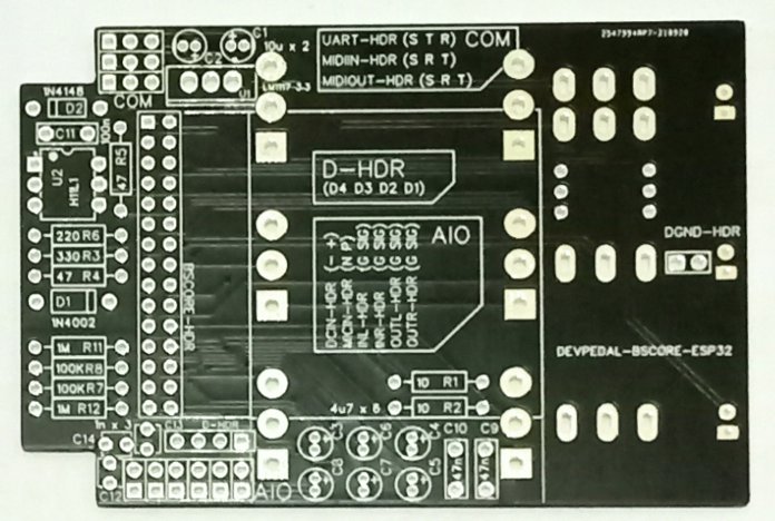
BGPM-1 circuit enable low-cost production for small scale (from single to 100 pedal units) because it supports flexible arrangement of some control knobs. BGPM-1 PCB has 6 pads of knobs in 2 rows arrangement, designed for 125B enclosure. The first row can be mounted with potentiometers (up to 3 pots), while the second row can be mounted with pots, SPDT switch (2- or 3-position selector switch), or 1P8T rotary switch. The PCB support MIDI in/out function, stereo in/out, and microphone input. Just keep in mind that although it has microphone support, the available space doesn’t allow XLR socket for a standard microphone input. If you need a standard XLR input for microphone, you can use the Model-2 which has more space for the XLR socket since the PCB doesn’t has MIDI in/out support. Here is the schematic diagram (Figure 12):
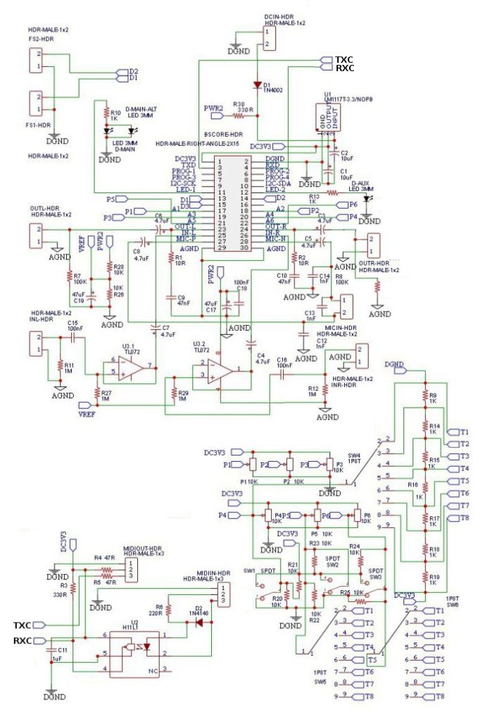
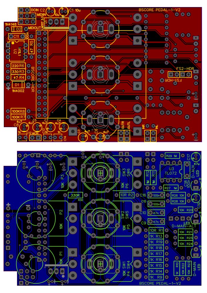
Figure 13 shows the PCB for this circuit, it shows a double side design with component mounting and soldering in both side. This PCB is still already tested for PONG pedal (polyphonic octaver and noise grabber), and the gerber file download is available in this page: https://github.com/hamuro80/blackstomp/blob/master/hardware/Gerber_PCB_BGPM_1_V2.zip
I.6 BSCORE Generic Production Model-2 (BGPM-2) Circuit Schematic Diagram
BGPM-2 circuit is designed to provide enough space of an XLR socket for microphone input. It still has pads for 6 control knobs in 2-row arrangement, but the second row doesn’t support for potentiometers mounting. The support for MIDI in/out has been removed to provide the extra space needed for XLR socket mounting. Here is the schematic diagram (Figure 14):
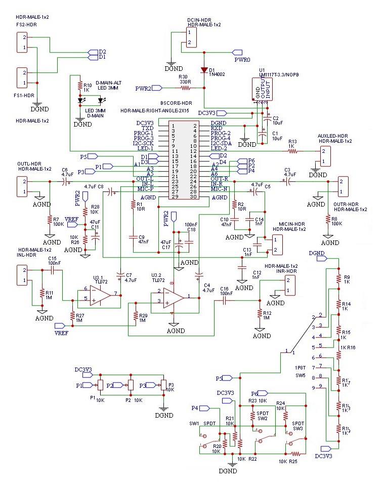
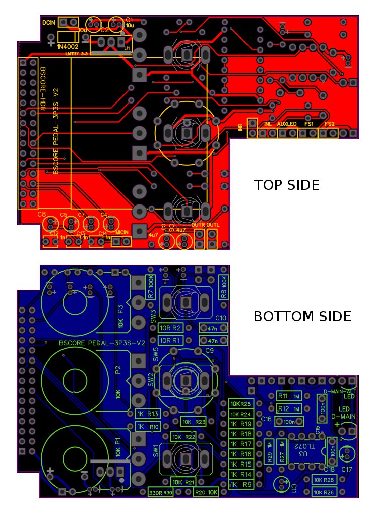
Figure 15 shows the PCB for the model-2 circuit, BGPM-2 PCB, it shows a double side design with component mounting and soldering in both sides. This PCB has been tested for vocoder pedal application, and you can download the Gerber file in this page (find the download button): https://github.com/hamuro80/blackstomp/blob/master/hardware/Gerber_PCB_BGPM_2_V2.zip
I.7 BSCORE Development and Production Model (BDPM) Circuit Schematic Diagram
To accommodate both development and production model in one PCB, a BSCORE development and production model PCB is designed (BDPM PCB). The schematic diagram of the BDPM circuit is shown in the Figure 16, and the assembled board is show in the Figure 17. To get the BDPM board:
- Design the printed circuit board of BDPM circuit and send it to the PCBA manufacture to get the board assembled.
- Buy the BDPM board in Deeptronic’s Store and get the complete fabrication files (Gerber files, pick and place files, BOM, etc.) as the bonus, so you can use it for your own mass production later.