Electronic Relay Circuit Breaker Protects Boost Converter from Short Circuit and Overload
Boost Converter and Its Unprotected Nature
Boost converter topology, where an inductor is alternately shorted to ground by a switching transistor in some portion of the cycle and connected in series with the load in other portion of the cycle, is inherently unprotected from load failures such as short circuit and overload (look at the figure 1 of the reference [1]). The switching controller and the final switching transistor might be protected using current sensing and feedback mechanism to switch off the transistor at all time, but the power source path still connected from the input to the load through the inductor. The current limiter in a boost circuit will work but it only decrease the voltage output to the same level of the source voltage, works to limit the current at some point, but after that point it won’t work on lower load resistance or short condition.
Electronic Circuit Breaker Using Relay
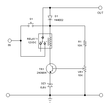
To provide short circuit and overload protection, some circuit uses fuse to break the connection between the circuit and the power supply. The drawback of a regular fuse is that once it get blown then we must replace with the new one. To make a “reusable fuse”, we can design a electronic circuit breaker. Since it has same function with regular fuse, sometimes it is called electronic fuse as well. Here we present such circuit which is designed for boost converter for laptop backup supply using lead acid battery, but actually it can be applied for any power supply protection by modifying some component values to suit the custom specification of the targeted power supply. The electronic circuit design is shown in the figure 1, with the components values selected for laptop/notebook power supply application which has fixed voltage rating of 19V or 20V.

Figure 1. Hamuro 19V Relay Circuit Breaker
How The Circuit Breaker Works
This circuit breaker should be installed in a power supply system with current limiter or where a voltage drop will be detected to deactivate the relay. The basic principle is that a relay contact is used to connect the point where the load is connected, and the coil of the relay is powered from the that point itself. At the first time the power get “on”, the relay coil should be manually triggered by bypassing the relay contact through push-button, and once activated the power source will be kept connected to the loading point by the relay contact. When a load is shorted or overdraw the current, the voltage at the power supply line will be dropped from its nominal voltage rating, and the voltage supplying the coil will be insufficient to keep the relay say “on”, and now the relay get turned off, disconnecting the load (which is in short or causing overload condition) from the power supply. The relay has normally wide voltage tolerance, so it’s not reliable to set the breaking point, for example a 12V relay might still work on 8V supply, so we make an electronic circuit to make the relay sensitive to voltage drop. The Zener diode is used to make the biasing point higher, and to drop the voltage across the relay to be 12V. The VR1 and R1 is configured as voltage divider [2], employed to adjust the tripping point of the relay.
References: