Music Controlled Disco Light Circuit with Automatic Level Control
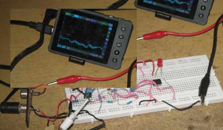
Figure 1. Assembled Hamuro Automatic Level Disco Light Controller Circuit
Introduction to Automatic Disco Light Control
Simple audio or music controlled disco light uses comparator to sense the beat of a music signal, but this comparator has a reference point that should be calibrated according to the music signal volume. It’s easy if we have a light jockey to take the duty of controlling all the lighting, but it’s not the solution what we present here. Here we design a fully automated setting for the music’s beat detection, so it will works for any sound signal level, from weak phone output to high wattage loudspeaker outlet, it do the leveling automatically.
The Idea Behind The Circuit
I got this idea when developing a computer-based light controller, where it should control a lighting hardware to drive disco lamps following the music-beat from MP3 file. It that software, I make a special algorithm to remove the critical manual adjustment for the threshold of the beat detection. A beat in music signal is characterized by prominent amplitude change, going above the average. When we set the average level for the threshold level then we get the dynamic beat output which can be used to drive the disco lamp. Instead of setting this level manually, I make this as dynamic reference by picking it from a long term moving average of the music signal. It’s easy for me to make the hardware (electronic circuit) version of the software, since actually a modeled the audio processing algorithm based on a electronic circuit in mind.
Figure 2. Schematic Diagram of Hamuro Automatic Level Disco Light Controller Circuit
The Electronic Circuit Design and The Schematic Diagram
The schematic diagram is shown in the figure 2. It consist of two moving average amplitude detectors, each with different time constants. These two detectors are built using transistors and some passive components. The transistor is configured as a rectifier-buffer, an emitter follower configuration. A voltage variation in its base will be followed by the emitter voltage, but only for the positive cycle. At negative cycle, where the base is going down below the zero then the emitter voltage is held at zero. Look at the R2 and R3 junction for the base bias, it is shorted to ground through a silicon diode 1N4148, so the voltage will be dropped to around 0.6V, the same with the base cut-off level. This biasing level put the transistor in a “ready-to-conduct” condition, to enable small signal detection of the music input. Finally look at the difference between both moving average amplitude detector circuits, you’ll see it only on C3 and C4. They determine the time constants or the periods of the moving average amplitude detection. Note that in all level, whether you drive the input from monster power amplifier or from from tiny headphone amplifier, there always be difference signal in the fast moving average and the slow one. The discrimination on both fast and slow moving average signal produce a music beat signal, an it is done by the comparator U1.
Operational Amplifier Selection for The Comparator
(To be continued..)