Modular Fastest Quiz Controller Circuit Using Relays
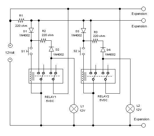
Figure 1. Hamuro’s Fastest Quiz Controller Circuit Using Relays
Introduction
Fastest quiz controller is basically a switches controller, the switches are then used to control lamps and or alarms, which are designed to make indication of who is the first contestant that push the knob first, so the host can give the question for him. Many circuits of such controller are available on many websites, but here we present our design that employs only relays as the active components. Other interesting feature of this first quiz controller design is the modular configuration, which means that we can easily expand the number of the modules which corresponds to the number of contestants. See the schematic diagram of the circuit in the figure 1.
How The Circuit Works
There are two modules shown in the schematic diagram. To analyze how this circuit works, first we can identify that there are three wiring lines that connected to all modules. The first line is ground, the second is supply, and the third is current-limited supply (let’s call it triggering line). The triggering line is employed to provide enough voltage for initiating relay activation, but the line must be safe if it is then shorted to ground after activating any relay. Lets take a look at one module, say RELAY1. The coil is connected to the triggering line through a diode an a push button. After RELAY1 is triggered, one contact of the relay shorts the triggering line to ground, and the other contact connects the supply line to its coil to keep RELAY1 stay activated after the triggering line is grounded. After loosing competition to get pushed first, the other modules are prevented to be triggered because the triggering line is now shorted. D1 is employed to prevent the current from D2 being shorted to ground when keeping the RELAY1 to stay “on” as long as the push button is held contacted after winning the competition. D2 is employed to prevent the current flow from triggering line to the output of the module: the indicator lamp or alarm. The resistor value is determined by the relay coil resistance, using voltage divider formula:
VR =(VS-VD)RC/(RC+ R),
R = ((VS-VD) RC/VR)-RC,
VR is the voltage rating of the relay (5V), VS is the supply voltage (12V), VD is the bias voltage of the diode (0.6V), and RC is the coil resistance. See the circuit demonstration in the video channel below: