Simplest Relay Flasher Circuit with Better Stability
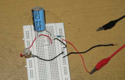
Figure 1. Assembled Relay Flasher Circuit
A flasher circuit with only three components (relay, capacitor, and resistor) is very popular design, which is advertised as the simplest design for relay flasher. I don’t know who is the designer of this circuit but the schematic diagram is spread on many websites. Here is one example, using 12V relay, 220Ω, and 2200uF capacitor for building 12V flasher circuit. Now we present here the same circuit, but we make different components selection for better stability.The schematic diagram of the circuit is shown in the Figure 2.
Figure 2. Simplest Relay Circuit’s Schematic Diagram
How Relay Flasher Circuit Works
At unpowered condition, the relay contact which connect the power supply to the controlled bulb is open, an a small charging current flows through bulb, relay coil and capacitor, and resistor. This current is small enough so that the bulb doesn’t light. The C1 capacitor voltage is increasing and after some period, the voltage at C1 capacitor reach the level of activation voltage of the relay. At this level the relay is getting activated and the relay contact is closed, connecting the bulb directly to the power supply and get flashed. While this relay is getting activated, the capacitor is discharged through relay coil and R1 resistor, and the voltage is gradually decreasing. After reaching the relay’s deactivation voltage level, the relay contact is then opened again, disconnecting the bulb from power supply, and then the charging cycle is repeated just like as the beginning. The relay doesn’t oscillate at high frequency since there will be different voltage level of activation and deactivation of the relay, means that once a relay get activated at some point, it will get deactivated some distance below that point. This phenomenon is called hysteresis in continuous response case or a dead zone in case of binary or discontinuous response. Thanks to this phenomenon, and we’re lucky to get this since it is often considered as a bad situation in other system.
Better Stability with Components Selection
With this very simple circuit, is there any optimization we can do for better performance? Of course we can do it by selecting the best component value for each components.
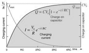
Figure 3. Capacitor Charging Chart
The main component’s characteristic which define the stability of the flashing period over the supply voltage variation is the capacitor charging. If we use 12V relay, its activation voltage vill be about 8V, or about 3/4 point at vertical axis. At this point a small variation of the input voltage will produce a scaling up or down the chart, and this produce relatively larger variation at time (horizontal axis) than if we use 5V relay (which has activation voltage about 4V). This variation can be large at automotive application, since it can range between 10 – 14.5 Volts at various battery condition. Using lower relay voltage means also that it needs lower wattage requirement for the bulb to make the flasher works. It also more reliable since the flasher will keep working in the lower supply voltage although it becomes unstable. The only drawback for this optimization using 5V relay is that we need higher capacitance value for the capacitor to get the same period with using the 12V relay, but this is what we have to pay for better stability and reliability. Finally, we can show the performance of this more stable relay flasher circuit in our video at our Youtube channel below, just watch and try out yourself, good luck!