More Complex Chasing Light Controller Using Relays
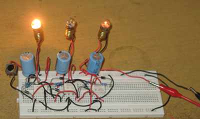
Figure 1. Hamuro’s Complex Moving Light Controller Using Relays
Producing More Perceptible Light Movement And Lowering The Power Consumption
Chasing light controller presented in our previous light controller circuit has very simple design. It control three lamp power lines to make moving light effect by turning on two lamps and turning off one lamp in sequences. Now I have designed new moving light controller circuit which turning on only one lamp in cycle of three lamps. This would produce more perceptible light movement effect and lower overall power consumption.
The Circuit’s Schematic Diagram and How It Works
The schematic diagram of the circuit is shown in the Figure 2. The whole system consist of modular units. This moving light controller system can be extended by adding more modules to make longer lamp cycle, if you wish. Each module is basically a set reset flip-flop which is designed using relay as the active component.
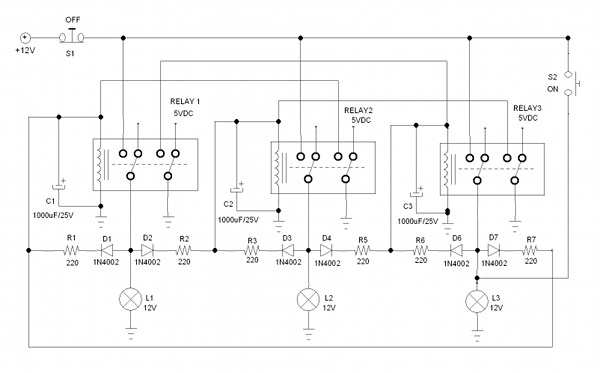
Figure 2. Hamuro Complex Relay Moving Light Controller Circuit Schematic Diagram
Look at the rightmost module, it consist of one DPDT relay (RELAY3), diode (D4,D6), resistor (R5,R6), and capacitor (C3). To set this module, the positive side of D4 should be tied to Vcc to charge C3 capacitor. When the voltage at C3 capacitor reach the activation voltage of the relay then it get activated. After activated then D6 get tied to Vcc and now the relay is maintained to stay “on” forever, until the module get reset. This module get reset when its relay coil get shorted to ground, and this is done by other module. This third module (RELAY3) is reset by the first module (RELAY1). At the first time the circuit get connected to power supply, all modules are in non-active condition. To start one of the modules, a push button S2 is pressed to initiate the activation of first module (the leftmost, RELAY1). After the first module has been activated, it then try to activate the second module because now D2 is tied to Vcc. After some period then RELAY2 get activated and this bring two action: deactivating the first module (by shorting its relay coil) and activating the third module (by connecting the diode D4 to Vcc). After some period then the third module get activated and do the similar things as the previous module.
Controlling High Power Line Voltage
If we want to control powerline voltage (110/220 AC wall outlet) then ideally we have to use triple poles double throws relays (relay with 11 pin), so we can use the third set of the contacts to control the line voltage, giving a fully isolated control. If we have only DPDT relays (as shown in the schematic diagram) then we can still control high voltage line by replacing the 12V bulbs with 12V relays to get fully isolated control of line voltage (110/220VAC).
Components Selection
The relays are 5V types, so we can measure the coil resistance and then use the value as the base to compute the limiting resistor values (R1,2,3,5,6,7). The limiting resistor which is serially connected with the coil (with internal resistance) will make a voltage divider configuration, so the resistor value should be chosen to make Vrelay/Vcc = Rcoil/(Rcoil + Rlimiter) equation is satisfied. When 5V relay is not available then we can still use 12V relays since they will actually be activated below 12V, just measure the actual activation voltage by applying variable voltages to investigate the real lowest activation voltage. The capacitor determine the speed of the chasing light, we can use higher value for slower speed. The speed is also affected by the applied supply voltage, see the video on our Youtube channel below to the effect, as well as the effect of pressing and holding the starting button. Try it yourself and good luck!