Low DC Voltage (12VDC) Fluorescent Tube Lamp Circuit
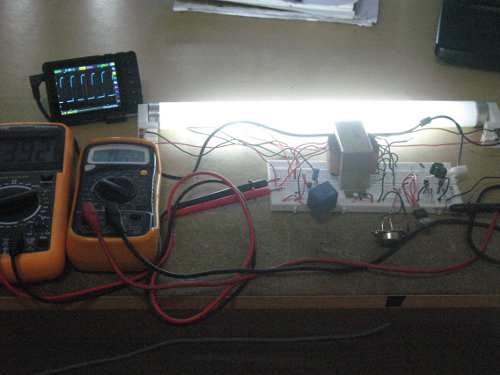
Figure 1. Fluorescent Tube Lamp Circuit
A fluorescent lamp, also called a fluorescent tube is a tube with electrodes filled with low pressure mercury-vapor, utilizing fluorescence to generate visible light. The excitation caused by electric current in the gas of mercury vapor generate short-wave ultraviolet light. There is phosphor coating inside the tube an the ultraviolet light then make this coating glows. Conversion of electrical energy into the visible light in a fluorescent lamp is much more efficient when compared to incandescent lamps, ranging from 50–100 lumens per watt, several times the efficacy of incandescent bulbs.

Figure 2. 12V DC Fluorescent Lamp Circuit Schematic Diagram
Fluorescent tube lamp works similar to a Zener diode. Before excitation, the tube has high impedance, but once the gas ionization is excited then the resistance drops and acts as being shorted. In powerline application, this tube is wired in series with a ballast coil to limit the current. The a low voltage application, the voltage should be stepped up above the ionization voltage to make it works.
The circuit shown in Figure 2 provides voltage conversion and starter mechanism. The circuit consist of astable multivibrator around TR1 and TR2, current switch TR3 and TR4, and starter around TR5. The transformer is actually a one ampere step-down 220V to 12V, but we reverse it by using the secondary as the primary. At the first time the circuit get powered, the starter circuit turns the RELAY1 on and the filament inside the tube is connected to 12V voltage source, warming up the one side of electrode for 1 second. See the working circuit in the Youtube video channel below: