Classic Two Transistor Alarm
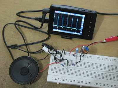
Figure 1. Assembled Classic Two Transistor Alarm Circuit
A very simple alarm circuit can be built using two transistors and several passive components. We don’t know who is the inventor of this circuit, but it usually presented in many old electronics books, so let’s call it “classic”. This simple circuit implement complete function of an alarm, which is nothing more than an oscillator with high enough power to drive a loudspeaker. A principle of oscillator circuit is that its structure consist of amplifier with positive feedback. The gain of the amplifier should be more than unity (unity gain = 1). You can use small transistor about 50-100 mA maximum collector current with 100 or more DC gain (hFE).
The Schematic Diagram and How It Works
Figure 2. Two Transistor Alarm Circuit’s Schematic Diagram
The circuit consist of cascaded direct DC coupled amplifiers. The first transistor TR1 is biased by R3 resistor, then its collector current is connected directly to the base of second transistor TR2 for biasing. To make the circuit oscillates, a feedback path is provided through C3 and R4. Without the feedback path, the biasing current is selected to be low enough so there transistors wont get saturated. Look that the bias is a propagated from R3 to drive TR1, and TR1 to drive TR2. This produces small current pulse at TR2 in the beginning, but this current is continuously fed back to TR1 through C3 and R4 to produce bigger and continuous pulse oscillation. C1 is provided to make a gradual bias current for TR1 base, results in gradual change of oscillation frequency. If you omit C1 capacitor the the circuit will produce a flat tone. The speed gradual frequency changes is determined by the value of C1 capacitance, select a smaller caps for faster changes. The frequency (when flat without C1) or the frequency range (with gradual sweep by C1 existence) is determined by C3, and you can replace it with smaller caps for higher frequency.
Alarm Circuit Action in Video
We can watch how the assembled circuit behaves when powered activated. Below you can watch it in our Youtube channel, and you can see the generated waveform at the loudspeaker in the oscilloscope. It looks like pulses with fixed width but has variable repetition rate.