Multi-Channel Expansion Oversampling: 15Bit from 12Bit ADC
Introduction: Analog-to-Digital Conversion Oversampling
Every analog-to-digital conversion is designed for specific resolution depending on the bit (binary digit) width of the conversion. For example, a 10 bit ADC with 5V reference would have 5V/1024 resolution or about 4.883 mV. The intrinsic error related to the resolution is the digital-quantization error of ±0.5 bit. In other words, it should produce only ± 2.441 mV error in the case. In order to improve ADC resolution while maintaining fast conversion and simple circuitry, a multi-channel expansion oversampling method is presented here.
Noise Addition in Oversampling Method
Generally, we can do oversampling by reading the input several times. Then, add the input with a noise that moves the input up and down across 1 bit level. Finally, convert the signal many times and then average them to get more consistent reading at the expected new resolution (bit-width). Without noise addition, a very stable signal on the input would produce a consistent reading. As a result , no matter how many times we repeat the reading, averaging them won’t increase the resolution.
The ideal source of the noise would be a Gaussian white noise, but the generation of this noise is complex. If the noise is truly random, the noise component for each samples would spread evenly within 1 bit width of the original ADC resolution. This ideal condition enable the system to improve the resolution by 1/2 bit if we double the sampling frequency. In real application, the oversampling frequency should be much higher than this ideal condition. It is because the random nature of the noise wouldn’t be distributed evenly for small number of samples. As presented in the reference [1], oversampling would work when some complex conditions are satisfied:
- The noise must approximate white noise with uniform power spectral density over the frequency band of interest.
- The noise amplitude must be sufficient to cause the input signal to change randomly from sample to sample. Moreover, the change amounts is comparable to at least the distance between two adjacent codes (i.e.,1 LSB..)
- The input signal model is a random variable that has equal probability of existing at any value between two adjacent ADC codes.

Complexity of The Simple Solution
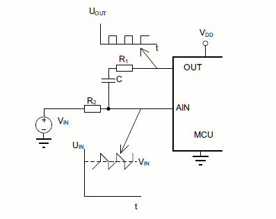
A simple quasi-triangular noise shown in Figure 1 is proposed in reference [2] to avoid complication in white noise generation. The circuit is simple, but other complexities are introduced:
- The peak-to-peak amplitude of this quasi-triangle signal should be exactly 1 bit width or its multiplication. This lead to calibration problem which is difficult for such small noise amplitude. Please comment on this my opinion if I’m wrong.
- The quasi-triangle signal frequency should be uncorrelated with the sampling frequency if the oversampling period is longer than this additive signal period.
- Faster oversampling is possible if we acquire all the over-sampled samples within one period of the quasi-triangle signal. But, consequently it requires the noise signal should be very stable to give consistent time boundary. Otherwise, we should implement a synchronization method for reading the samples.
Multi-channel Expansion Oversampling
Schematic Diagram of The Circuit
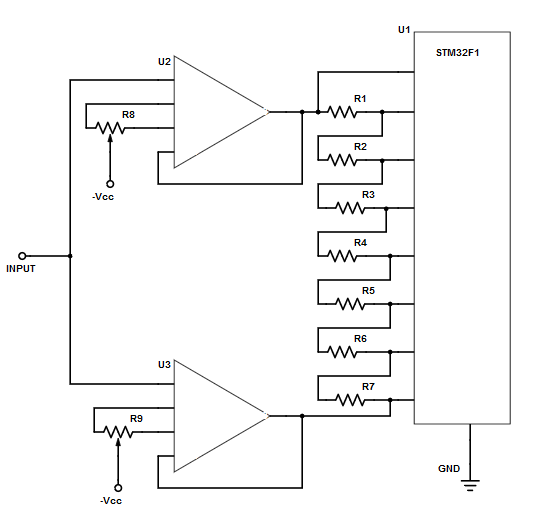
Wict such complexity of the oversampling method as previously described, I have designed this circuit for multi-channel expansion oversampling. This circuit expand one voltage level point into 8 voltage level points. In order to work with this circuit, the microcontroller should have multiplexer for implementing multi-channel inputs (such as STM32F1 series). In short, the circuit expands the input signal into several points that ranges from (signal -0.5 bit) to (signal + 0.5 bit). Figure 2 shows the schematic diagram.

The employed operational amplifiers should have offset adjustment. Therefore, we can set the first op-amp to give -0.5 bit offset and the second to give +0.5 bit offset. The ADC of STM32F1 series has 12 bit resolution with a fixed analog reference (3.3V). It means the bit width is 3.3V/(2^12) = 0.8 mV. With 8 channel expansion, the expected result would be 15 bit resolution or 0.1 mV resolution. In short, the multi-channel expansion oversampling range should be the bit-width of the original ADC resolution minus the bit-width of the expected final resolution. In other words, the voltage expansion should be 0.8mV – 0.1mV = 0.7 mV.
Calibration of Multi-Channel Expansion Circuit and The Oversampling Conversion Reading
Using a high precision voltmeter, we can set the first op-amp to add -350 uV offset and. After that, set the second to add +350 uV offset. We should choose the voltage dividers R1 – R7 as low as possible. By doing so, we can minimize the loading effect of the multiplexer input. On the other hand, the cross-current between the first op-amp and the second op-amp outputs should be kept small. As a result, the op-amp would handle it easily. With only 700 uV difference, resistor values around 10-15 ohm results in total series resistance of 70 – 105 Ohm. It would produce the cross current in range of 6.67-10 uA, so it would be easily handle by the op-amp. To get the 15-bit reading, just sum up the reading of all channels, no need any shifting or division.
Simpler Circuit and Calibration Method
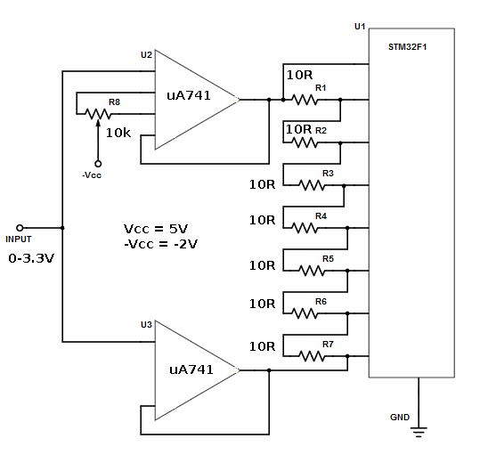
For lowering the cost and simplify the calibration process, R9 trimmer potentiometer can be omitted. We can then do the offset calibration by adjusting R8 only. Just make sure that U2 and U3 are of the same type to ensure that they have identical characteristics. While calibrating, we recommend that we keep the input level constantly at half of the reference voltage. After that, measure the voltage across U2 and U3 outputs and adjust R8 until gets 700uV reading. The modification that omit the second offset adjustment has been successfully tested. And the following figure shows the schematic diagram of the final circuit.

The -Vcc supply should be biased to negative in to enable the op-amp produce a correct result. Especially, this requirement is important for input condition at around zero volt. Finally, this multi-channel expansion oversampling circuit has passed final test using a positive supply to negative supply converter. The coverter is using 555 IC to drive a charge pump circuitry. And it produce around -2.5V supply from 5V positive supply. Update: this oversampling circuit has been employed in the design of Deepstomp, an open platform for DIY multi effect pedal.
References
- Improving ADC Resolution by Oversampling and Averaging, Silicon Labs Application Note, Rev. 1.3 7/13, 2013
- How to get the best ADC accuracy in STM32 microcontrollers, ST Microelectronics Application Note, 2017