Variable Dummy Load for Power Supply Testing
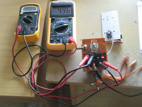
Figure 1. Assembled Variable Dummy Load
To test real capacity of a power supply, we need a load with variable current consumption. If we have high power variable resistor such as tapped wire-wound resistor, we can directly connect this resistor and make some measurement. Unfortunately, this kind of high power resistor is expensive and not so flexible getting wide adjustment range. Here is a simple solution using power transistor. This kind of dummy load is widely used in testing power supply. A Darlington pair is used to provide high impedance input since we want to use a low wattage potentiometer to vary the loading. Here is the schematic diagram of the circuit.
Figure 2. Variable Dummy Load Circuit Schematic Diagram
Building The Circuit
We have to install a heat sink for the transistor, since the transistors work in linear mode and dissipate a lot of heat. Soldering all components (except the transistors) on to a matrix board is the fastest way to build this circuit, it will be very easy because its simplicity. Use high amperage rating for Sw1, and use a convenient terminals to connect ampere meter, voltmeter, and the tested power supply. You can see in the Figure 1 that we use a speaker box terminal to ease the connecting and disconnecting the ampere meter, voltmeter, and the power supply.
Components Selection
The components in the schematic diagram is not so critical. The first parameter we should defined is the maximum current and voltage that our dummy load will handle. Let’s say that we need a dummy load that can be set to draw maximum of 3A from 24V power supply. Here some steps to ease the selection process:
- Choose the final transistor that capable of handling the maximum current and voltage, a 2N3055 will be safe since it handle max 60V and 15A. Using D313 as the final transistor will be unsafe since it handle only 3A at maximum.
- Choose R2 resistance value. let say we choose 1 Ohm, then the wattage will be square of current times the resistance, we get 9 watt, and we can use 10W which is available on the market.
- Check the power dissipation at final transistor, make sure it can handle. With 3 amperes through R2, it means the voltage across R2 is current times the resistance = 3A * 1 Ohm = 3 volts, and the voltage between collector and emitter of final transistor is 24V-3V = 21V. The dissipates power a transistor is now 3A*21V = 63 watts. Now look at the power derating graph of the final transistor 2N3055. Find 63W point and trace at what degrees the case temperature should be maintained. We can see a point around 100°C, so we can easily maintain the heatsink temperature by immersing a half of bottom part of the heatsink into water. It is OK to left the water boils during few minutes usage. Don’t like getting wet? Just use a big heatsink and fan!
- Check the base current and voltage to operate at maximum rating by dividing the collector current with the DC current gain of the transistor, choose a suitable transistor to drive in a Darlington configuration, or use a suitable potentiometer and resistor if it small enough. Cascade the Darlington configuration until we find a small enough wattage to be handled by a cheap potentiometer.
(Hamuro, October 2013)
Update (January 2014): Variable Dummy Load In Action
Watch the video of this assembled dummy load circuit on our Youtube channel below: