Ressettable Electronic Fuse (Circuit Breaker) Circuit for Securing General Power Supply
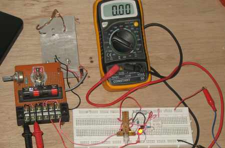
Figure 1. Assembled Hamuro’s Electronic Fuse/Circuit Breaker Circuit
Electronic Fuse
Fuse or circuit breaker is useful to protect electronic circuit, especially the power supply. A short circuit or overload might damage the power supply if the connection between the power supply and the load is not immediately disconnected. When we use conventional fuse, we must replace the blown fuse with the new one after fixing the failure which cause the short or overload. This would be costly if the situation makes frequent occasion of the case, such as in circuit testing or experiments. A laboratory power supply for example, it will be big benefit if we provide a reusable “electronic fuse” which can break up the power-supply connection in case of short circuit or overload, and it can be reset to connect again after the short or overload failure has been fixed. The schematic diagram of the circuit is shown in the figure 2.
Figure 2. Hamuro Electronic Fuse Circuit Schematic Diagram
The Electronic Circuit Design and How It Works
The circuit uses a relay as the main contactor. The position of the S1 switch shown in the schematic diagram is the normal position. Other position of the switch is reset position. At the first time the power supply is connected or powered, the current stops at the relay contact and not going anywhere. We should switch the S1 to reset position so the power source is bypassed and the circuit get powered. After get powered, the relay is then get activated and now the S1 switch can be turn back to its normal position. Now the circuit is kept powered through the relay contact. The relay coil is powered via TR1 transistor, which is biased by R2 resistor. The TR2 transistor in non active since there voltage across R3 is below 0.6V at normal condition, when there no short circuit or overload. Note that the output get the power source through this R3 resistor, so no matter how much is the current drawn by the load, it will always be sensed by the resistor. If the voltage across this sensing resistor go over 0.6 volts then the TR2 transistor will get activated (switched on) and this will turn of the TR1 transistor. Turning off this transistor means turning off the relay coil, and finally disconnection this electronic fuse circuit and the load from the power source. If the failure that cause the short or the overload has been fixed, this electronic fuse can be reset by switching the S1 to reset position and then switch back to the normal position.
Customizing The Current Limit Specification
The determining component for current limit value is the R3. The voltage across R3 is the product of the current multiplied by the resistance. Since the activation voltage of TR2 is about 0.6 volts, then the value of R3 should be chosen as 0,6/current limit. If we want a 0,6A limit then use a 1 ohm resistor, or if we want a 6A limit then use 0,1 ohm resistor. The wattage should be the product of 0.6v times the current. For 6A limit, the wattage should be 6A x 0.6V = 3.6W, so a 5W resistor should be sufficient. The resistor R1 is used to lower down the voltage to 5V since the relay is 5V. We can use a 12V relay and omit this resistor. See the circuit performance in our Youtube video channel below: