Automatic Wah/Quack Effect Using LED+LDR Controlled Band-Pass Filter
Introduction to Automatic Wah/Quack Effect
Automatic wah/quack effect gives a similar effect with the manual version (reference [1]), but without the need of any pedal to manually control the frequency/tonal sweep.
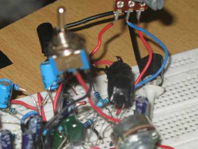
Figure 1. Hamuro Auto Wah Effect Circuit Assembled in Bread Board
This automation is made possible by detecting the envelope signal of the instruments audio signal, and use it to control the filter to produce center frequency sweep, producing audio tonal sweep which sounds like “wah” or “quack” pronunciation. From the reference [2], envelope detector is defined as follows:
An envelope detector is an electronic circuit that takes a high-frequency signal as input and provides an output which is the envelope of the original signal.
An example of a signal and its envelope is show in the figure 2, showing the original signal in the blue plot, and its envelope in the reds.
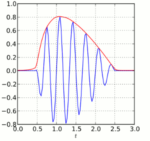
Figure 2. A Signal (Blue) and Its Envelope (Red)
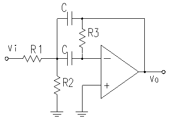
Figure 3. Band-Pass Filter Circuit Schematic Diagram
The Signal Processing Core Circuit
The core function for building automatic wah/quack effect is band-pass filter. This signal processing function produces the effect of sliding vowel as heard in the “wow” or “quack” pronunciation. Figure 3 shows the schematic diagram of second order band-pass filter. The center frequency of this band-pass filter is determined by the value of resistors and capacitors. The advantage of this circuit is that we can shift the center frequency by shifting the value of R2 without changing the characteristic of the gain (the maximum gain value at the center frequency), see reference [3] for more detail.
The Complete Auto Wah/Quack Circuit’s Schematic Diagram
Figure 4 shows the complete schematic diagram of wah/quack effect, consisting an internal ground reference (U1A), an envelope detector (U1B), an envelope amplifier (U1C) and a modified band-pass filter (U1D).
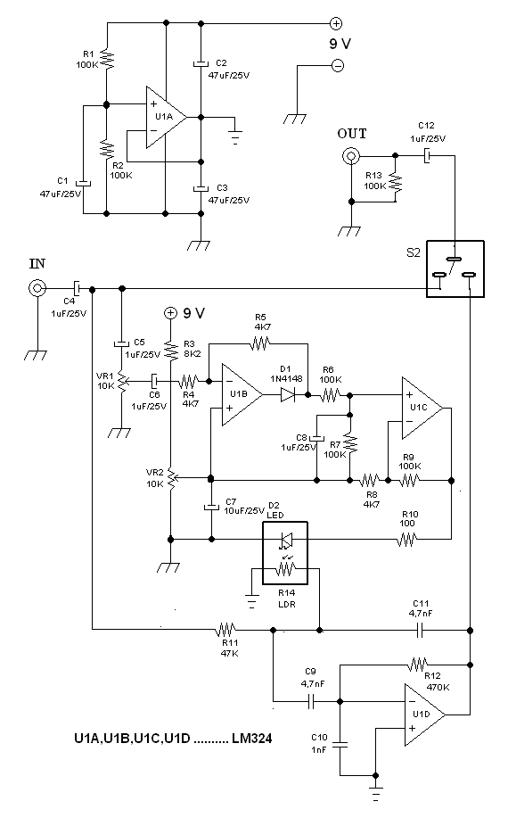
Figure 4. Hamuro Auto Wah/Quack Effect Circuit Schematic Diagram
Internal Ground Reference
The operational amplifier U1A is employed to stabilize a reference point called “internal ground”. The internal ground concept is used here to give separated internal ground reference, different from external ground reference. As you can see in the schematic diagram, there are two types of ground symbol, first is the internal ground symbol with horizontal strips (connected to the output of U1A), and the second is the external ground symbol with diagonal strips (connected to power supply, input, and output grounds). Please beware of this separation!
Envelope Detector
The envelope detector function is provided by the circuit around U1B, which can be separated into rectifier and filter parts. The rectifier part is a modification of precise full-wave rectifier circuit from reference [4], consist of U1B, C5, C6, VR1, R4, R5, and D1. At the negative cycle of the input, the output of the op-amp will be positive and the D1 diode will conduct to give an output which is fed back to the inverting input through R5, giving the exact copy of the mirrored input at the D1 output since the gain is unity (R4=R5). At the positive cycle of the input signal, the op-amp output becomes negative and D1 will be disconnected, so the input will directly be routed to the output (the connection between D1 and R6) through R4 and R5. Because of the loading effect of R6 and R7, this cycle will be about 9% lower than the opposite cycle (when the op-amp actively drives the D1 diode), but it’s fine for this function. The filter part consist of R6, R7, and C8, smooth out the ripple to give a smooth envelope profile.
Envelope Amplifier, LED Driver and Offset
Without amplification, the envelope signal ar C8 capacitor has very low amplitude and very weak power, not ready to drive a LED (light emitting diode). Op-amp U1C provides amplification and buffering, driving D2 LED through R10 resistor. The gain of this amplifier is (R8+R9)/R8, giving amplification factor of 22.3 using the selected R8 and R8 values. You can increase R9 to 470K or decrease R8 to 1K to widen the frequency sweeping range adjustment by VR1 potentiometer. The frequency offset adjustment is given by VR2 potentiometer, wide enough to accommodate wide range sound color from bass to lead guitars.
The LDR Controlled Band-Pass Filter
The modification of a band-pass filter circuit is done by replacing a fix resistor with an LDR (light dependent resistor), which is exposed to the light of the envelope-controlled-LED. The filter is build around U1D components, and a 1 nF capacitor is added to short the op-amp’s inverting input to the ground, limiting the high frequency response in a trade of high frequency stability of the op-amp operation. In the experiment of the circuit, it uses a bright red LED and a small CdS LDR, and the resistance transfer from LED’s current to LDR’s resistance is shown as follows:
|
1 2 3 4 5 6 7 8 9 10 11 12 13 14 15 16 17 18 19 20 21 22 23 24 25 26 |
0,020 mA 672K ohm 0,050 mA 164K ohm 0,10 mA 62K ohm 0,30 mA 15K ohm 0,5 mA 8K ohm 0,7 mA 6K5 ohm 1,0 mA 4K4 ohm 2,0 mA 2K5 ohm 3,0 mA 1K8 ohm 4,0 mA 1K4 ohm 5,0 mA 1K2 ohm 6,0 mA 1K1 ohm 7,0 mA 1K ohm 8,0 mA 932 ohm 9,0 mA 865 ohm 10,0 mA 807 ohm 11,0 mA 760 ohm 12,0 mA 722 ohm 13,0 mA 685 ohm 14,0 mA 657 ohm 15,0 mA 635 ohm 16,0 mA 612 ohm 17,0 mA 593 ohm 18,0 mA 572 ohm 19,0 mA 557 ohm 20,0 mA 542 ohm |
Some experiments using different type of LEDs and LDRs give different result, but as long as they give resistance sweep from 100k to 2k inside the current range between 0-20 mA then we can use them. The LED and LDR should be tied face-to-face closely together, seal it with dark insulation tape to prevent ambient light leakage.
Adjusting The Frequency Range and The Frequency Offset Knobs
To get the best result, two adjustment is provided: frequency range dan frequency offset. The frequency range knob is VR1, and the frequency offset is VR2. First, turn the frequency offset to its minimum (when the signal is grounded, no envelope signal should be detected from any volume of musical instrument signal). At this condition, play your instrument and adjust the frequency offset knob to get the low or base sound color. After getting the proper offset then adjust the range knob while playing the instrument with dynamic power level (the strength variation of the plucking in case of guitar) to get the desired effect. See the circuit produce the effect in the video below:
References
- Manual wah/quack effect, https://www.deeptronic.com/inductor-less-wahcrying-babyquack-effect-using-operational-amplifier/
- Envelope Detector, https://en.wikipedia.org/wiki/Envelope_detector
- Active Band Pass Filter, http://www.electronicshub.org/active-band-pass-filter/#Multi_Feedback_Active_Band_Pass_Filter
- Single Supply Precise Full Wave Rectifier Using CA3140 Op-Amp, http://freecircuitdiagram.com/2008/09/15/single-supply-precise-full-wave-rectifier-using-ca3140-op-amp/