Component Twisting: Wiring Trick for Omnidirectional Bending
The Need for Component Adjustment
Have you ever bent some components to trim their position? But then you got your PCB‘s track and soldering pad broken? I’m sure many of you have ever done it, since there would be many reason to do. Some of them just do that for aligning to get better visual appearance. Or some others might do it for more serious purpose. Allocating space for other component, or trimming some LEDs to fit the hole of the enclosure for example. Here we will be introducing “component twisting” trick for electronic assembly.
The Problem: Breaking The Solder Pad of PCB
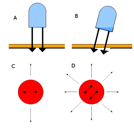
Take a look at Figure 1, a normal through hole PCB assembly for LED. This assembly is done by soldering its leads directly to the PCB with its straight leads (Figure 1 A). While this is a common assembly technique for two-lead components, it has a drawback. When we try to adjust its position in certain direction (Figure 1 B) then it could break up the PCB. In short, component with this kind of wiring/assembly can be moved only in one axis (Figure 1 C).
The Solution: Component Twisting
For developing multi-effect pedal prototype, I found a problem on how to fit many LEDs on its casing. Firstly, it should be kept simple by soldering it directly to the board. By directly soldering to the PCB, it means that we can avoid messy cables. Secondly, I got stuck in some ideas around how to bend its lead in certain shape. This shape should make the LED’s position adjustable in all direction, without breaking the board. Fortunately, after some hours of brainstorming, suddenly I got a simple trick.
First method is by twisting the component after soldered to the PCB, before fitting to the case/enclosure. To do so, just follow the following steps:
- Solder the component as a normal wiring/assembly (directly with its straight leads)
- Twist the LED’s body exactly 90 degrees after get soldered (before fitting into its enclosure).
The second method is by twisting the lead first before soldering. Off course you can choose between the first or the second method, whichever is more convenient.
The picture in Figure 1 D is a top view of an assembled LED on a PCB. In the bottom-left picture, the two right-left dots are the PCB holes. Differently, in the bottom-right picture it show more (upper-lower) dots. The additional two top-bottom dots are the points where the leads are attached in the LED body. And the connecting lines between two dots are the twisted leads. Now you can trim the LED/component body in all direction. Off course without breaking the printed circuit board, have a good day 🙂