Simple Running LED / LED Chaser Circuit Using 3 Transistors
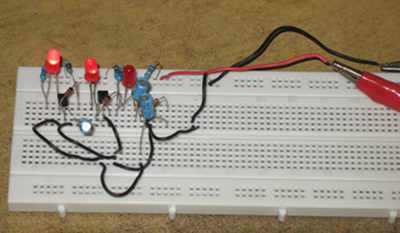
Figure 1. Assembled Hamuro Running LED Circuit
Running/Chasing LED Circuits on The Web
Running LED circuit, or sometimes called LED Chaser circuit, has very popular implementation using 4017 integrated circuit (IC). Almost all electronic websites has the circuit in their list of schematic diagram collection, you can check this dancing light circuit for example. The circuit based on that IC, is very flexible since its speed can be easily adjusted by changing the clock frequency, and its number of LEDs can be set between 2-10 by connecting the last used output to the reset pin. Talking about running/chasing LED circuit, then we have a question: is there any simpler alternative for running LED circuit without 4017 IC? Fortunately the answer is Yes!
Flip-Flop Circuit and Its Expansion
The idea of this rose in my mind years ago when I was in high school, when I learn a lot about electronics with very limited textbook, when I felt like studying magic where I should theorize myself on how circuits works by imagining how electrons flow in the circuit, and the basic flip-flop circuit give me the idea to make a running LED. The basic flip-flop circuit has two sub systems (units) that turning on itself and turning off the other party in alternating turns. How about expanding this circuit to have three units and each unit is connected to turn off the next unit in circle? Look at the schematic diagram of the circuit below (Figure 2).
Figure 2. Hamuro Running LED Circuit’s Schematic Diagram
The circuit consists of three sub systems, call it a unit which built from one LED, one transistor, one capacitor, one zener diode, and two resistors. When we disconnect the connections of each unit from capacitor to the next unit, then each unit will be self powered and all LEDs will be turned on. Now if we then connect this capacitors then the active unit will try to turn off the other unit by shorting the base current to ground via capacitor to the active transistor.
Running The Circuit for Lower Voltage
A zener diode is added to each transistor base to make its turn-on level higher. Without this diodes, the LED won’t be fully turned off if we operate this circuit at 6V or higher voltage power supply. Off course you can omit these diodes if you want to operate this circuit using 3V batteries, lower the resistors R1, R3, and R5 if you do this. If you use the power supply with lower voltage (VS), and the LEDs with (VLED) forward voltage drop, the resistance value (VR) can be computed by selecting the current amount for the LED (IL), then find the resistance by (VS-VLED)/IL. Here the saturated collector-emitter of the transistor is neglected, since it will be low enough compared to VS and VLED.
Transistors Bias Asymmetry
If you look at R7 bias resistor, it gives different bias current for the transistor when compared to other transistors, and this gives shorter off period of LED3. This is not really good actually, but this asymmetry is needed to make sure the circuit won’t be stuck in balanced condition that give no oscillation. When all bias is balanced then this stuck condition is usually happens at power-on, then we have to make a “reset” by shorting one of any capacitors to empty the charge and make the circuit oscillates. Using asymmetric bias solve this issue, and what we do is by keeping the difference small enough to give fast enough starting oscillation of power-on but, not too perceptible on its timing variation of the flashing LEDs. Watch how the circuit works when assembled and powered in our Youtube video channel below and try it yourself, good luck!
Related Articles
- Running Lights Controller Using Relays: https://www.deeptronic.com/electronic-circuit-design/chasing-lights-controller-circuit-using-relays/
- More Complex Running Lights Controller Using Relays: https://www.deeptronic.com/electronic-circuit-design/more-complex-chasing-light-controller-using-relays/
Zener’s shown are reversed, remove them from the circuit. Change Vs to 3 – 5V
What you said is already mentioned in the article, that we can omit the zener if we want to lower the supply voltage below 6V. The zener polarity is not reversed.