Classic Alarm Circuit Employs Class-C Aamplifier for More Power
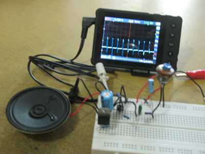
Figure 1. Assembled Circuit: Alarm Circuit with Added Class-C Amplifier
Basic alarm with small transistors presented in our previous alarm circuit article is usually enough for toys, but we might need more power if we wanna use it for automotive or industrial application. If you usually see class-c amplifier application in radio frequency circuit, then we will show you how it can be applied in audio circuit as well. From the Wikipedia, class-c amplifier is described as:
Class-C amplifiers conduct less than 50% of the input signal and the distortion at the output is high, but high efficiencies (up to 90%) are possible. The usual application for class-C amplifiers is in RF transmitters operating at a single fixed carrier frequency, where the distortion is controlled by a tuned load on the amplifier.
The Schematic Diagram of The Circuit and How It Works
This amplifier of this class can be implemented as very simple circuit, and even simpler in our specific audio application: to amplify audio frequency square wave signal. See the schematic diagram of the circuit in Figure 2. The circuit needs only three components: one transistor, one resistor, and one decoupling capacitor. When the signal at the base getting higher than 0.6V, the transistor TR3 begin to conduct, pull the diaphragm of the loudspeaker. On the other cycle, if the voltage at the base going under 0V (going to negative), the transistor will simply cut-off, releasing the loudspeaker diaphragm to its normal depletion. We can say that this amplifier is class-c because there will be inactive region between zero and 0.6V, a small part of the positive cycle, when the amplifier don’t produce any response.
Figure 2. Classic Alarm CIrcuit with Added Class-C Amplifier
The Alarm Circuit in Action on Youtube Channel
You can see how the circuit works and produce the sound when it assembled and get powered in our Youtube video channel. There you can see the signal in the oscilloscope has small negative spike, which come from loudspeaker’s back electromotive force when the current is abruptly stopped by the transistor. Check it out!