BSDEV-PDL Blackstomp Development-Mode Pedal Manual
Blackstomp is a digital audio effect processor development platform based on ESP32-A1S module. To speed up the effect pedal development cycle, Blackstomp provides a standard development-mode pedal to quickly test and run your application program. In this manual document, you will find the following information:
- I. Schematic Diagram
- II. Port and Knobs Layout
- III. External Connection
- III.1. Guitar/Line Input/Output
- III.2 Microphone Input
- III.3. MIDI I/O Connection
- III.4. Serial TTL Communication
- III.5. Expression Pedal, CV Input, or Button Extension
- III.6. Rotary Encoder
- III7. I2C OLED Display
- III.8. DC 3.3V Output
- IV. Firmware Program Loading
- V. Application Firmware Development
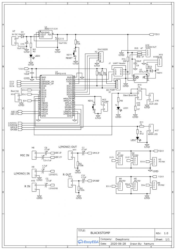
I. Schematic Diagram
- The schematic diagram consists two parts: onboard circuit and offboard parts wiring. Note that potentiometers (ctrl1-ctrl6) are considered as offboard parts (by the Blackstomp’s reference circuit), although BSMP-PCB provide onboard mounting pads.
- The schematic diagram in Figure 1. shows the onboard circuit, while the offboard wiring is show in the Figure 2.

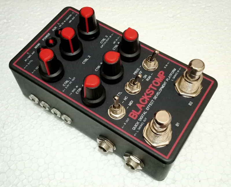
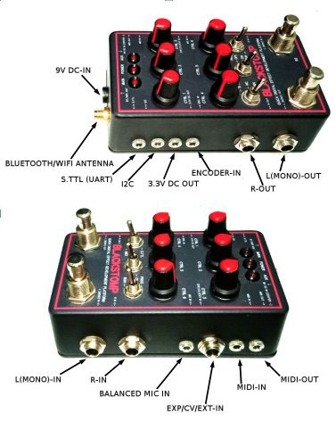
II. Ports and Knobs Layout
- The knobs and switches has clear labels that show their function, positioned close to each of their associated items.
- The labels for side-mounted is printed on the top, and the position is compromised to the available space. Refer to Figure 3 for clearer map of the side-mounted ports layout.
III. External Connection
III.1. Guitar/Line Input/Output
- L(MONO)-IN, R-IN, L(MONO)-OUT, and R-OUT ports use 6.3 mm TS (Tip-Sleeve) socket.
- The input output level is line-level standard, so it expects a maximum level of 1Vrms or about 2.8Vpp (peak-to-peak).
- The internal audio codec AC101 doesn’t specify the input impedance, but we can assume 20k-50k ohm for the guitar/line input. Any guitar pickup output should be fine for direct connection since the loading effect would just safely reduce the signal level, but pre-processing with a buffer or booster pedal would be better as long as the output level doesn’t exceed the maximum of the line-level standard (2.8 Vpp).
III.2 Microphone Input
- The microphone input port is a 3.5 mm TRS socket, so you might need 3.5 mm TRS to XLR for connecting your microphone to the pedal.
- Because the gain of the internal pre-amp is programmable, it will accept almost any type of microphones as long as it doesn’t require a phantom power.
III.3. MIDI I/O Connection
- The MIDI ports for both input and output employs a 3.5 mm TRS socket, wired to comply with the MMA standard (Type A/MIDI 2.0). We might need 3.5 mm TRS to MIDI (DIN) adapter depending on the connected device.
- Make sure the S.TTL/MIDI toggle switch is turned to MIDI position to enable the MIDI input/output ports.
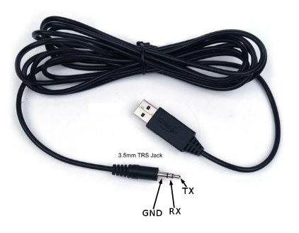
III.4. Serial TTL Communication
- Serial TTL communication is used for programming the firmware and displaying debug message (especially when the MIDI i/o is not used).
- The port uses a 3.5 mm TRS socket, so your USB-to-TTL converter/cable should have 3.5 mm TRS jack on the TTL end (see Figure 4).
- The TTL level is 3.3V, make sure the USB-to-TTL converter output level is 3.3V
III.5. Expression Pedal, CV Input, or Button Extension
- When a TRS jack is plugged to the port, the CTRL 2 potentiometer will be disconnected and the external input will be connected.
- Use analog expression pedal with 10k-20k potentiometer value for the best linear characteristic.
- The ring is wired to internal 3.3V source through a 330R resistor, so plugging a TS jack (for CV input as an example) will shot the ring to ground and 10 mA current will be safely grounded (and wasted).
III.6. Rotary Encoder
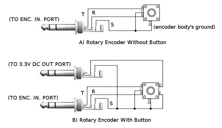
- WARNING: Never shot the 3.3V line (the tip terminal) to ground when accessing the DC out port!
- Rotary encoder without click button can be connected as shown in the Figure 4.A.
- Rotary encoder with click button can be connected as shown in the Figure 4.B. Note that the button is connected to the ring terminal, not the tip (which is the 3.3V voltage source) .
- Keep in mind that the input of rotary button is shared (in parallel) with the aux button/foot switch.
III7. I2C OLED Display
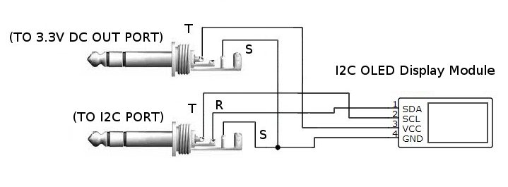
- WARNING: Never short the 3.3V line (the tip terminal) to ground when accessing the DC out port!
- Use I2C OLED display module with 3.3 V power supply and 3.3V logic signal level.
- Use TRS 3.5 mm jack for accessing 3.3V DC out, TS jack would short the ring terminal to ground and the aux button input would be in trouble.
- See Figure 4 for the OLED display module connection diagram.
III.8. DC 3.3V Output
- WARNING: Never short the 3.3V line (the tip terminal) to ground when accessing the DC out port!
- The 3.3V source comes from the same line of the system’s supply, no limiter or added protection.
- The only protection is the thermal and short protection feature of the employed voltage regulator AMS1117 (3.3V) .
- A brief short to ground would short the entire power supply of the pedal, including the power indicator LED, and would reset the system by power-on reset mechanism (after recovered from short condition).
- Frequent or long period circuit short event might damage the AMS1117 regulator chip or even the ESM32-A1S module.
IV. Firmware Program Loading
Using the Arduino IDE, we can load the firmware to the pedal using the following steps:
- Switch off the pedal (turn the ON/OFF switch to OFF position)
- Turn the MIDI/S.TTL switch to NC (not connected) position.
- Turn the PROG/RUN switch to PROG position.
- Turn on the pedal (turn the ON/OFF switch to ON position)
- Turn the MIDI/S.TTL switch to S.TTL position.
- Click the menu Sketch > Upload.
Refer to this documents for more information: Compile, Upload, and Run The Example Sketch
V. Application Firmware Development
- The application firmware development for Blackstomp pedal application can be done using Arduino IDE (integrated development environment) or ESP-IDF tools chain.
- For more detail about how to develop digital effect with Blackstomp, refer to the following documentation: BLACKSTOMP: Quick Development Platform for ESP32-A1S Digital Audio Effect Processor