BSCORE Dev Pedal (Blackstomp-Core Development Pedal) User Manual
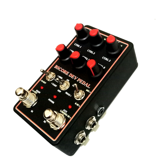
Table of Contents
- Knobs and Ports Layout
- External Connection
- Power supply
- Line/guitar input/output
- Microphone input
- MIDI input/output
- Wireless Connection
- Pedal Operation
- Running the effect pedal
- Programming the firmware
- Replacing the BSCORE processing module
- Hardware Circuit Reference
- Software Development Reference
Contents
1. Knobs and Ports Layout
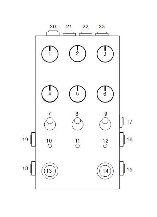
Knobs and Ports Description
- CTRL-1: Control knob for parameter-1
- CTRL-2: Control knob for parameter-2
- CTRL-3: Control knob for parameter-3
- CTRL-4: Control knob for parameter-4
- CTRL-5: Control knob for parameter-5
- CTRL-6: Control knob for parameter-6
- MIDI/UART Switcher
- At MIDI position: The MIDI ports (22,23) are enabled and the UART port (21) is disabled
- At UART position: The UART port (21) is enabled and the MIDI (22,23) ports are disabled.
- At N.C. position: Both MIDI and UART ports are disabled.
- Power Switch: Power the pedal ON or OFF
- RUN/PROG switcher
- RUN position: When switching-ON the power switch at this switcher position, the pedal will run the programmed firmware stored in the pedal.
- PROG position: When switching-ON the power switch at this switcher position, the pedal will run a bootloader to reprogram the pedal with new firmware through UART port communication.
- Main LED Indicator: The function is defined by the running effect application.
- Power LED Indicator: Turned ON if the power supply is supplied and the power switch is ON.
- Auxiliary LED Indicator: The function is defined by the running effect application.
- Main Foot Switch: The function is defined by the running effect application.
- Auxiliary Foot Switch: The function is defined by the running effect application
- L (Mono) Input: Left-channel input or mono input (with guitar pickup or line level)
- R Input: Right-channel input (with guitar pickup or line level). Depend on the running effect application, this input might be disabled by the application for mono operation.
- Microphone Input: Balanced microphone input through 3.5 mm TRS socket.
- L-Output: Left-channel output
- R-Output: Right-channel output. Depend on the running effect application, this output might be disabled by the application for mono operation.
- Power Supply Input: DC Power supply input (9V DC, 350 mA -500 mA, negative at the center)
- UART Port: Serial communication port for firmware programming and debugging
- MIDI-Input: The MIDI function is enabled or disabled by the running effect application firmware
- MIDI-Output: The MIDI function is enabled or disabled by the running effect application firmware
2. External Connection
- Power Supply
- Voltage 9V DC (+- 10%), with negative at the center of 2.1 mm plug.
- Use 500 mA (at minimum) AC/DC adapter when using Wi-Fi or Bluetooth transmission.
- Use 350 mA (at minimum) AC/DC adapter when only uses BLE (Bluetooth Low Energy) or no wireless transmission at all.
- Line/Guitar Input/Output
- Use standard 6.35 mm mono jack for all input-output plugs
- Input level range: 1 Vrms (2.83 Vpp)
- Input impedance: depends on the installed BSCORE module, for BSCA1SES8388-MOD will be about 40k Ohm
- Output Impedance: < 1k Ohm
- Microphone Input
- Balanced microphone input without phantom power
- Socket: 3.5 mm TRS (tip: positive input, ring: negative input, sleeve: ground/shield)
- MIDI Input/Output
- Socket: 3.5 mm insulated TRS socket
- Wiring: MMA Type A/MIDI 2.0 standard
- Make sure the UART/MIDI switcher is turned to MIDI position to enable the MIDI input/output ports.
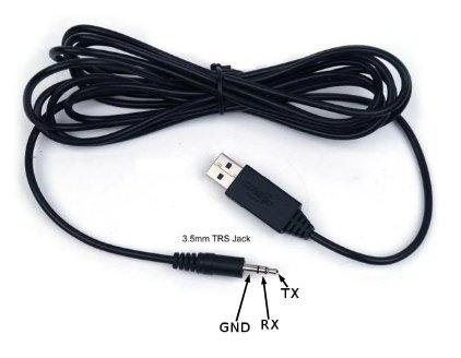
- UART Port
- Function: flash (firmware) programming and software debugging port
- TTL level: 3.3V
- Socket: 3.5 mm insulated TRS
See figure 3 for the USB-TTL adapter cable- Tip: Receive (RXD) at the pedal end, transmit (TXD) at the programming device (PC) end
- Ring: Transmit (TXD) at the pedal end, receive (RXD) at the programming device (PC) end
- Sleeve: digital common ground
- Wireless Connection
- The wireless connection is configured by the running effect application firmware, so it might enable or disable the Bluetooth or WiFi connection.
- When the wireless connection is enabled then be cautious of the following:
- Make sure the 3D-printed PLA base-lid (comes with the pedal) is used for securing the enclosure, so the wireless signal can be transmitted and received in and out of the enclosure through this radio-transparent base-lid.
- Keep the distance of the wireless-connected device less than 2 m for reliable data transfer.
- Avoid placing the pedal on a metal base because it blocks the wireless signal transmission, placing on a wooden table or wooden pedal board is recommended when wireless connection is in use.
- Adjust the position and the direction of the pedal and the wireless-connected device if the received signal is too weak.
4. Pedal Operation
- Running The Effect Pedal
- Turn the power switch (8) to OFF position, MIDI/UART switcher (7) at MIDI position, and RUN/PROG switcher (9) at RUN position.
- Plug all the needed external connections (guitar in, effect-out, AC/DC power adapter, etc.)
- Turn the power switch (8) to ON position. Now the power LED indicator (11) will light and the pedal will be fully operational in less than 2 seconds.
- Programming The Firmware
To program or reprogram the firmware of the pedal, we have to run the Arduino IDE or the ESP-IDF’s flash programmer utility on a computer or PC, and connect it to the powered pedal via USB-TTL converter cable (to the UART port), then do the following steps:- Switch off the pedal (turn the ON/OFF switch to OFF position)
- Turn the MIDI/UART switcher to N.C. (not connected) position.
- Turn the PROG/RUN switcher to PROG position.
- Turn-on the pedal (turn the power switch to ON position)
- Turn the MIDI/UART switcher to UART position.
- Execute your flash programmer task from the PC, for example click the menu Sketch > Upload if you are using Arduino IDE.
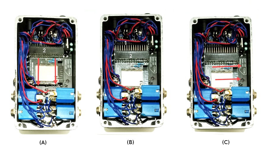
- Replacing The BSCORE Module
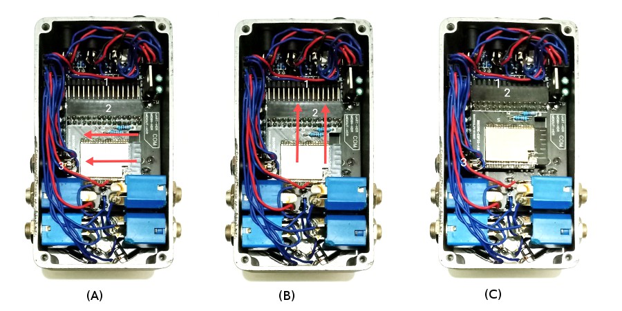
BSCORE Module can be easily replaced by unplugging the old module (shown in the Figure 4) and plugging the new one (shown in the Figure 5).- BSCORE Module Uninstallation
- To remove the module, pull the module as shown in the figure 4(A) to unplug the male header (1) of the main board from the female header (2) of the module.
- After the header is completely unplugged as shown in the figure 4(B), slide the module to the right as shown in the figure 4(C), so we can lift the module out of the enclosure.
- BSCORE Module Installation
- To install new module, slide the BSCORE module under the microphone socket (3) like shown in the Figure 5(A), so the female header of the module (2) is perfectly aligned with the male header (1) of the main board.
- Push the module to plug the male header (1) of the main board to the female header (2) of the module as shown in the figure 5(B). Push the module until it get perfectly plugged like shown in the figure 5(C).
- BSCORE Module Uninstallation
5. Hardware Circuit Reference
- BSCORE Development Mode Pedal Schematic Diagram
- BSCORE Module’s Schematic Diagram
- BSCORE Module’s Pinout Specification
- Blackstomp Core (BSCORE) Module’s Physical Design Specification
Hello,
I am very glad I found your site with these great products! I am trying to develop a effects device for guitar. Ultimately, the effect sound should be transmitted wirelessly, with best possible ( low) latency. Have you ever tried that ? And, Is the wireless option of the esp32 still usable, whaen its inside that metal enclosure ?
I am willing to by a DEV Pedal, thanks and all the best,
Michael
I’m sorry but the implemented BLE library is impossible to stream the audio output because it has slow transfer (about 2KB/s). There is classic bluetooth protocol which might has faster speed but not implemented in the Blackstomp library, and I’m not sure about the noise interference if you can implement it. Wifi transfer might be the faster option but it’s not implemented in the library, you can implement yourself if you know how to code but again I’m not sure about the noise interference to the audio.
The the BLE test from the metal enclosure works only if the back-plate is replaced with 3D-printed PLA material, and it the coverage is limited to 1-1.5m.