High Voltage Flip-Flop With SCR and Low Voltage Components
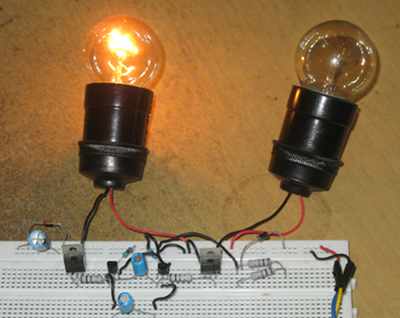
Figure 1. Assembled High Voltage Flip-Flop Circuit
With only few components, we can use resistors, diodes, and capacitor, we can convert line voltage (220VAC) directly to low DC voltage (10 VDC). This low voltage powers the low voltage flip-flop standard circuit, but this circuit is then used to drive high voltage SCR. This simple high voltage flip-flop circuit can be used to control alarm lamps, bell, or any alerting high voltage indicators. The schematic diagram of the circuit is shown in Figure 2, shows the components symbols and the wiring connection. The SCR type can be chosen as shown in the label, but various high voltage SCR type can be used for this as well. The capacitors C2 and C3 determine the blinking frequency, so you can increase the value to get slower blinking rate, and decrease the value to get faster blinking rate. The lamp or the load should be compatible with rectified half cycle power supply, since the SCR allow the current to flow in one direction only. Resistor R4 should be 2W type, since this resistor dissipates power as heat. Beware that this circuit is not isolated from high voltage powerline, so don’t touch any conductor while this circuit is powered to avoid electrical shock hazard. We can use 5-500W light bulb with this circuit, but the delivered power would be a half of the bulb spec. Watch the video of the circuit in action at our Youtube channel as shown in the video link below, and try yourself at home with safety precaution!
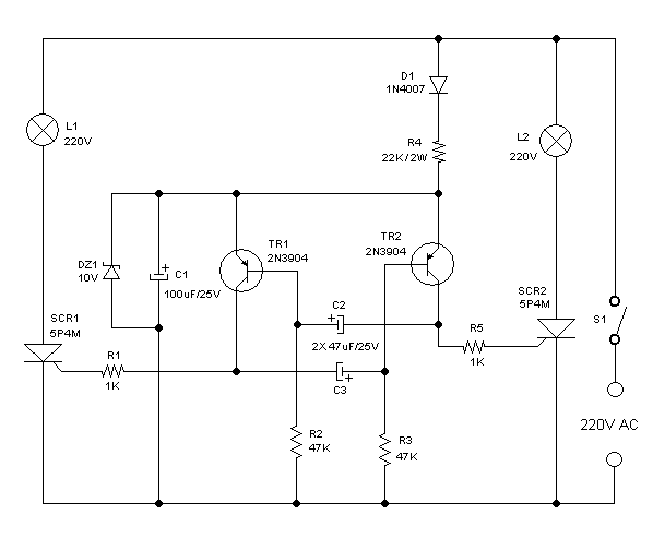
Figure 2. High Voltage Flip-Flop with SCR and Low Voltage Components
Please explain me, how the above circuit can switch off the scr ?
And please explain the whole circuit working concept.
thks