Direct Reading Inductance Meter Employs Triangle Wave Generator
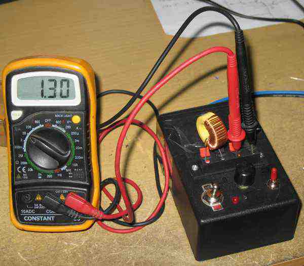
Figure 1. Assembled Hamuro Inductance Meter Circuit
Inductance and The Measurement Unit
Inductance is a property of electric conductor, and it expresses the characteristic of generating electromotive force or voltage when the amount electric current changes inside it. It looks like a concept of inertia of mass in the mechanical domain when it generate force if the speed of its movement is changed. The unit of inductance measurement is called henry (H), which is described as follow: One henry is an inductance that generate one volt electromotive force when the rate of current change is one ampere per second.
Measurement Methods Survey
The very basic of measurement will be applying a voltage to an inductor and measuring the voltage and current change in it. It can be difficult because we have to use fast and precise instrument to make the measurement with this basic method.
One popular method is by inserting an inductor into an oscillator circuit, then we measure the frequency of the oscillator’s output to computer the inductance of the inductor. It works because an LC (inductor-capacitor) oscillator will produce oscillation frequency which is inversely proportional to its inductance. We can use a frequency counter of frequency-to-voltage converter to measure the oscillation frequency. Direct reading of this method should have microcomputer or micro controller to compute the division, which is difficult to be done in analog circuit. Division operation in analog will be expensive to do since the circuit will be sensitive to temperature drift. One simple solution for analog circuit is by limiting the measurement in small range and replace the division operation by complementing the signal using inverting amplifier.
Other popular method is done by connecting the inductor to form a voltage divider, fed with alternating current signal. The measured voltage will be proportional to the reactance of the inductor, which is proportional to inductance and the frequency of the signal.
The methods of measuring inductance while keeping the circuitry simple and low cost will always an interesting challenge to many circuit designer. I’ve seen other method that use a square wave signal applied to an inductor, which generate a voltage spike in every positive edge of the square wave signal. This spike pulse will have variable width which is proportional to its inductance, this spike is then fed to a comparator (or simple logic gate) to generate pulse-width modulated signal.
Chosen Method: Back to The Basic
To enable calibration using available standard instrument (oscilloscope, multimeter) we approach the basic method to avoid providing standard inductors to calibrate our meter. We want a good accuracy without providing accurate inductors as reference for calibration, since we don’t know how to get an inductor with exact 1 mH or 100uH inductance value. Please note that we don’t invent any new method, since inductance measurement using triangular wave has been widely done in lab experiment to study the inductor. They usually use a function generator to generate triangle wave signal, and put an inductor in series with a resistor to convert the voltage signal into current signal. Here we should choose a resistor with high resistance value relative to inductor’s expected reactance in order to make the system behaves more like ideal current signal. In an attempt to make a better performance, we use active circuitry to make a triangular current signal to improve the linearity in a wider measurement range.
The Electronic Circuit Design
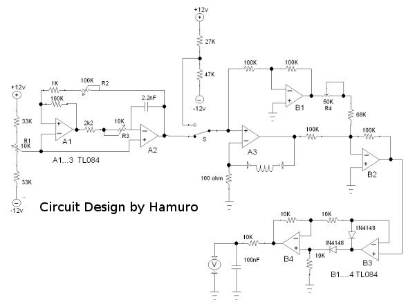
Figure 2. Hamuro Inductance Meter Circuit Schematic Diagram
The circuit’s schematic diagram is shown in Figure 2. The system consist of triangle wave generator (op-amp A1, A2), voltage to current converter (op-amp A3), null adjuster (op-amp B1, B2), and active rectifier (op-amp B3, B4). The oscillator uses a standard triangle wave which employs an integrator and Schmidt trigger, but we add offset adjuster R1 to make sure the output is symmetric in respect to the ground. The op amp might produce asymmetric signal since the Schmidt trigger might have asymmetric high and low output voltage swing. The oscillator is set to 100kHz to provide one measurement range (2uH to 200uH). The amplitude of the triangle wave is set to 5Vpp (peak-to-peak), giving +2.5V at high peak and -2.5V at low peak. The op-amp A3 convert this signal into 50mA/0,05ms current change rate. Using basic inductor formula, this current change should produce a 2V voltage for 200uH.
Since the output of op-amp A3 is the sum of voltage across 100 Ohm resistor and the voltage of inductor, then we have to extract only inductor voltage to measure and read it as inductance value. If we look further detail of inductor voltage, we realize that the voltage is not only caused by inductance but also caused by its internal resistance, since an actual inductance always have equal series resistance (ESR). To ease the analysis, the output voltage of Op-amp A3 is assumed to be consist of inductance voltage and resistance voltage. The inductance voltage is a pure square wave and the resistance voltage is a pure triangular wave. If ESR = 0 then the resistance voltage will have exactly same shape and amplitude with triangular wave input, and when the ESR > 0 then the resistance voltage will have same shape but higher amplitude. To remove the resistance voltage, the original wave is inverted by op-amp B1, scale the amplitude by potentiometer R4, and then added to op-amp A3 output. After addition with the inverting triangle wave at op-amp B2, we get the extracted inductance voltage at B2 output. The signal is then rectified using active full-wave rectifier (op-amp B3, B4) to get DC voltage reading.
It’s not clearly shown in the schematic diagram of the circuit, but the supply voltage for the op-amp is ±12V symmetric supply. We use 7812 and 7912 popular voltage regulator IC for this circuit, and we can expect not more than 50mA is drawn from both positive and negative supply.
Calibration
To calibrate this inductance meter circuit, first we have to short the inductor testing terminal using 0 ohm cable, and connect the output to a voltmeter at 2V range. Then make sure the triangle wave signal at A2 output is swinging symmetrically. This can be done by adjusting R1 while measuring the output voltage using DC voltmeter. Set this voltage to 0V since symmetrical triangle wave would produce zero volt for DC voltmeter reading. The next step is setting the amplitude of triangle wave signal at A2 output to be 5Vpp (-2.5V to +2.5V), this can be done by adjusting R2 while measuring the output using oscilloscope or AC voltmeter. Make sure that the shape of triangle wave is perfect. The final step is setting the oscillator to give exactly 100kHz triangle wave, and this is done by adjusting R3 trimmer potentiometer. Use an oscilloscope or frequency counter to do this. After this calibration step, we can unshort the testing terminal and now our inductance meter is ready to be used.
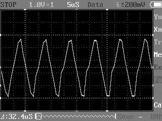 Figure 3. A3 Output, Inductance Voltage Plus Resistance Voltage, Testing A 47uH Inductor
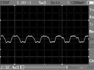
Figure 4. B2 Output, Pure Inductance Voltage, Testing A 47uH Inductor
Measurement Procedure
To measure an unknown inductor, connect the inductor to the testing terminal, turn the switch S to upper position (to be connected to a voltage reference). Adjust the potentiometer R4 to give 0 volt reading, or set it to get the lowest possible reading if it fail to zero the output. Now turn the switch S to lower position (to be connected to oscillator output), and the inductance value can be read at the voltmeter with conversion rate of 2V per 200uH or 10mV per 1uH.
(Hamuro, Yogyakarta October 2013)
Update (January 2014): The Assembled Inductance Meter Circuit in Action
Watch the assembled circuit in our Youtube channel below: