Audio-Controlled Disco Light Controller Circuit
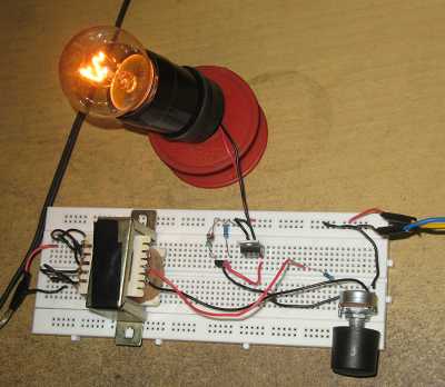
Figure 1. Assembled Audio Controlled Disco Light Circuit
Using some active and passive components, we can build a simple audio-controlled disco light controller circuit. A standard audio power amplifier output, which usually drive loudspeaker, can used to drive this disco light circuit. With this circuit we don’t need light jockey anymore, because the flashing of the light will be directly controlled by the music signal itself. The schematic diagram of the circuit is shown in the Figure 2.
To ease the explanation, the circuitry can be grouped into several functional parts (sub-systems). First, the input interface and isolation circuitry, consist of audio jack and small power transformer. The small power transformer is chosen since the input-output audio transformers are getting rare this days, so we can use almost any small power transformer (around 100-350mA). This sub-system does the signal transfer while isolating the high line voltage from the audio input equipments. Please be aware that the safe-to-touch part of this circuit are only the input jack and its connected side of the transformer, the rest are dangerous!
The second part making up the system, is the attenuator, consist of fixed resistor R1 and variable resistor VR1. The adjustment of the variable resistor controls the proper biasing level of the TR1’s base, which is finally controlling the triggering level of the SCR 5P4M. Look at the picture of the assembled circuit, the variable resistor (the potentiometer) is installed with a plastic knob to avoid the lethal electric shock!
The third part is the buffering rectifier TR1, which provide more stable drives for the final driver SCR1. This circuit is powered by series resistor R3, which is limited to 9,1V by DZ1. This resistor and diode doesn’t filter the ripple of the half-wave rectified voltage, it act just like a limiter that limits the voltage at 9,1V, it is fine since the SCR will keep active until the gate voltage down to zero, regardless of the gate voltage stability.
The last part, is the final drive, the SCR itself. It provides the switching function of the disco lamp power. The type of the SCR is not critical, as long as you choose the right voltage and amperage rating then it will be okay. Just search the datasheet of the locally available SCR types to make sure it fits your need.
Figure 2. Schematic Diagram of Audio Controlled Disco Light Circuit
The video of this working circuit can be seen at our Youtube channel below, make sure you know the safety precaution before making up this project at home, do it at your own risk!