16-bit Audio PWM by Dual 8-bit PWM with Auto Calibration
Introduction: PWM (Pulse-Width Modulation) for Digital Audio Conversion
Pulse width modulation (PWM) technique has been widely used for converting digital audio stream into audio signal since it is very simple and easy to implement. Many low-cost micro controllers include dedicated PWM controllers as their standards, and many engineers use it for many purposes. In this article, we present the solution for 16-bit audio PWM output that features the auto-calibration for better accuracy.
PWM in Microcontroller
In microcontroller, the PWM controller is implemented as timer or counter. It runs continuously to increment the counter at every clock tick and reset every time the counter reach a certain configurable value, the PWM period. Each time the counter value is incremented, it will be compared with the PWM active factor value to get the output. If the counter value is less than this active factor value then the output will be “high”, and will be “low” otherwise.
This result in a controllable pulse width (by the active factor value) that spans during the counter increment from zero to the active period (when the counter value is less than the active factor). This active factor, or simply called as PWM value. This value can be then get updated regularly with audio stream data. As a result, the PWM output will reproduce the audio signal. After that, that an active or passive filter would remove the PWM frequency component (1/PWM period). This filtering is posssible since the PWM frequency is much higher than the audio frequency components. A block diagram shown in the Figure 1 represents most microcontroller’s PWM module implementation.
How it Works: Pulse Width Control Mechanism
The clock source is normally configurable to select the clock from many sresources. For example, the clock prescaler is configurable to provide more frequency option. And it works by dividing the clock source by the prescaler values. The reload/reset value controls the reset circuitry to automatically reset the counter. It happens when the module is running in a counting up mode and the counter value reach the reset/reload value. If the module is running a counting down mode, a zero-overflow trigger will auto-reload the counter with the reset/reload value. This trigger comes when the counter overflows from decrementing the zero value. As a result, the counting down will restart from the reloaded value. In short, this reset/reload value will determine the PWM period.
Resolution and Speed Limitation
Please note that the PWM period put a limit on the PWM resolution. In other words, more resolution means lower PWM frequency, and lower resolution means higher PWM frequency. For example, let’s take a look at STM32F103 microcontroller. It has 16 bit counter for PWM generation, and we can configure the source to provide maximum of 72MHz clock. This clock is the signal source that increment the PWM counter. If we want a 10-bit resolution, then we can set an auto-reload/reset value of 1024 for the PWM period. So, we get a PWM frequency of (72,000,000/1024) Hz or 70.312 KHz.
We can increase the resolution to 11-bit and we will get 35.156 KHz PWM frequency. Increasing for more resolution results in an unacceptable speed. Since the PWM frequency affect the audio quality, then it should be much higher than the sampled audio signal’s frequency. Sometimes it is acceptable to have around 15 KHz audio bandwidth (half of the PWM frequency) with 11-bit resolution. However, it won’t be acceptable in professional audio or recording studio standard.
Dual 8-bit Module for Producing 16-bit Audio PWM
To improve the PWM frequency and the resolution with the limited hardware, we can use two PWM modules. You can use two 8-bit resolution PWM generators in parallel configuration. In order to work, you need to sent the most significant byte is sent to high byte PWM. After that, you can send the least significant byte the lower byte PWM.
To connect both PWM modules, attenuate the output of the lower byte PWM by 1/256 factor. Then, you can mix it with the high byte PWM output. Figure 2 shows the block diagram, which I first saw in audio software codec for STM8S application note.
Auto-Calibration for Dual PWM Audio Output for STM32F103 Microcontroller
Schematic Diagram of The Circuit
The dual PWM circuit shown in the Figure 2 is very simple. However, attenuating the low byte PWM output with such small factor of 1/256 require high precision resistors (R1, R2). Firstly, the resistor value proportion of R1 and R2 should be exactly 1:256. Secondly, we just couldn’t find a single resistor with such exact value. And lastly, even it exists, then it always has some deviation within a range of toleration.
To allow the calibration within the software, a lower resistor value (220k) is intentionally selected. This resistor controls the low byte PWM ouput attenuation resistor, as shown in the Figure 3. In this case, I design the circuit for STM32F103 microcontroller. It has 3.3V operating voltage, and more importantly, this microcontroller uses the same voltage level for PWM output and ADC conversion reference. The amplifier and filtering circuit employs LM324 as the active component. This op-amp is suitable since it works with 5V voltage supply. Moreover, its output is capable of swinging down to (almost) zero and up to 1.5 Volts below its supply voltage.
16-bit Audio PWM Calibration
The calibration procedure should be implemented to adjust the auto reload/reset value to lengthen the PWM period. Consequently, the transition of low-PWM from 0x00 to 0xFF would produce the same increase by smallest increment of the high-PWM. With 12 bit ADC resolution, the chosen gain (16x) will be adequate. The U4 amplifier converts the lowest 12 bits of the combined PWM into the full range of the ADC input. So, it enables the calibration by adjusting of the low byte PWM period.
Above the 0x0fff, the output of U4 amplifier would be higher than 3.3V. When this happens, the Zener diode D1 would start conducting. As the result, it will protect the microcontroller chip by dropping the volatge. With this condition, the calibration works only in hte range of 0 – 0x0fff (of the cascaded PWM output). However, It is assumed that after the low byte PWM period has been calibrated within the first 12-bit range, then the similar performance would be achieved when the high byte PWM goes above that range.
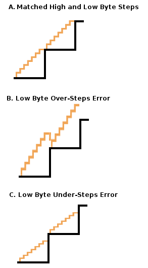
Missing-Steps and Over-Steps Error
A gain mismatch of the low byte PWM period would result in either missing-steps or over-steps errors. For illustration, take a look at Figure 4. for example, to see the error. It’s a simplification since the illustration reduce the low byte steps to 8 steps (3 bits). When the lower resistance value is chosen for the R2, then an over-steps error (Figure 4. B) would be produced. This would be what happen if the low byte PWM period is lower than the expected. In the other hand, higher period (than expected) would result in missing-steps error (Figure 4. A). In short, a calibration method should be implemented to minimize this error. And all we need to do is adjusting the low byte PWM period to get the proper value.
Practical Calibration Method
To minimize the missing-steps and over-steps errors, we have to do calibration routine that adjust the low byte PWM period to the optimum value. Firstly, with the amplifier circuit providing 16x gain (U4), the step-size of the high byte steps can be measured for all of the first 4 bit steps. As the result, there would be 16 levels of high byte increment for optimizing the calibration. Secondly, we can measure the overall low byte steps by flipping the low byte PWM period from 0x00 to 0xFF and vice versa, for each levels. It is possible that not all 16 levels is usable for calibration since the 16x amplifier is uncalibrated. Consequently, some top levels might be useless since it get saturated. To detect this saturated condition, just look if 12-bit ADC reading gets the saturated value (4095) or not.
UPDATE: Final Circuit After Testing (10/10/2018)
After constructed and tested, D1 Zener diode has significant current leakage before reaching its breakdown voltage (3.3V), and it should be omitted. Fortunately, the application note [reference 1] of STM32 series would accept positive current injection (up to some level) without affecting its conversion precision. The 10k resistor R7 is sufficient to limit the current while maintaining the input series resistance low enough. With low resistance, consequently, fast charging of the hold-capacitor inside the analog multiplexer in the microcontroller will produce faster conversion. The final note, that the -Vcc of the operational amplifier should be sourced below the ground. While LM324 operational amplifier can swing almost down to the ground, however the current source and sink capability would be very low without the negative supply. Here is the final circuit:
Further update, for example of a more practical application of this 16-bit audio pwm circuit, we have developed a diy multi-effect platform employing this design. Take at look at Deepstomp pedal overview here.
References:
[1] AN2834 Application Note: How to get the best ADC accuracy in STM32 microcontrollers, STMicroelectronics
[2] Audio Software Codec for STM8S, STMicroelectronics Application Note.