Flasher Circuit with DPDT Relay Works for Any-Wattage Load
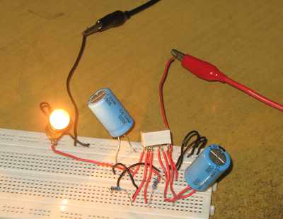
Figure 1. Assembled Hamuro DPDT Relay Flasher Circuit
Introduction
Classic series relay flasher circuit usually need minimum wattage for the connected load to work. Beyond the specified minimum wattage, then the flasher will not work or become unstable. Here I designed a simple solution using DPDT relay, that works for loads with any wattage.
The Circuit and How It Works
The circuit need one DPDT relay, two resistors and two capacitors. The schematic diagram of the circuit is shown in Figure 2.
Figure 2. Schematic Diagram of Hamuro DPDT Relay Flasher Circuit
At relay-off condition, C1 capacitor is charged through R1 and C2 capacitor is charged through R2. Now look at C2 capacitor, since R2 is smaller than R1, C2 will be fully charged to reach supply voltage (12V) before C1 reach the relay activation voltage (about 8V). After a period of time, the voltage at C1 will reach the activation voltage of the relay. After the activation of the relay, now the bulb is connected to the power supply and get flashed. To make this flashing last longer, at this cycle the C2 is connected to C1 (in parallel withe the relay coil), this make the C1 continue to be charged by C2 since C2 has higher voltage (12V). All of this charge of C1 and C2 is then consumed by the relay coil for some period of time until it decreased to the level of relay deactivation voltage. When deactivated, the bulb is turned off and the cycle of charging both capacitor is repeated.
How to Select The Resistors Values
The R1 and R2 resistors must be selected to make sure the circuit work. First we need to measure the internal resistance of the relay coil. This can be done using standard multimeter, and let’s designate this value as RL. Using supply voltage VS (12V) and relay voltage VR (5V), the maximum value for R1 resistor should be selected in order to make the voltage divider of R1 and RL, a voltage of VR should be generated when connected to the supply voltage VS. R2 resistor is employed only to limit the current to avoid current rush. Sometime this short-like condition can make the relay contactor get latched and the circuit operation will be erroneous. The principle is that C2 should be charged faster than C1 so when the C1 has reach the relay activation voltage then C2 should have been fully charge to VS. The minimum of R2 can be computed based on the maximum current handling of the relay and the voltage supply. If the relay maximum current is 10 ampere and the power supply is 12V, then the minimum of R2 is 1.2 ohm. For simple grab, we just select R2 as half of R1.
DPDT Relay Flasher Circuit in Youtube Channel
Here you can watch how the circuit works when assembled and powered in our Youtube video channel. See the circuit in action, try it yourself and good luck!