Fold-Back Distortion: Producing “Phew” Effect Using Software and Hardware (Analog Electronic Circuit)
Introduction: What is Fold-Back Distortion?
I was introduced to a term of “fold-back distortion” in the past by an article from an old book which I forget what the title is, but the book contains schematic diagrams of many circuits collected from old publication of Elektor magazine (www.elektor.com). The article presents the circuit’s schematic diagram and how it works. I can’t exactly remember the details of the circuit, but I still remember how it works. Figure 1 shows three different signals, (a) is the undistorted sine wave, (b) is the clipped, and (c) is the folded one.
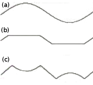
Figure 1. Three Signals, (a) Undistorted Sine Wave, (b) The Clipped, and (c) The Folded
An undistorted sine wave, shown in the Figure 1 (a), produce a clean sound. When the wave is just clipped, as shown in the Figure 1 (b), the sound get distorted, producing a harsh sound, but the prominent frequency component is still the base frequency. When the signal above the clipping point is not just clipped but folded-back, as shown in the Figure 1 (c), the prominent frequency becomes two times of the base frequency, producing a unique effect when the original signal dynamically comes at high amplitude (above the fold-back point) and then gradually decreased down to silence, making a transition from double-frequency to pure base (original) frequency dominance.
Fold-Back Distortion in The Natural Phenomenon
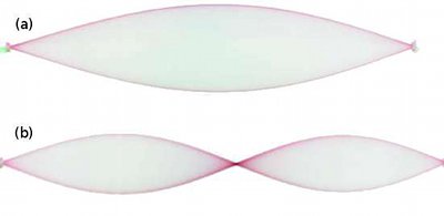
Figure 2. Rubber String, (a) Plucked Gently, (b) Plucked Hardly
I can’t find any reference about how a fold-back distortion is related to a natural phenomenon, but I remember when I was a kid, playing with a loose rubber string attached to a used box (as a resonator). It produced an unstable frequency “phew” sound when it’s plucked hard, and it produce a soft stable frequency when it’s plucked gently. Sometimes, plucking it hard even producing a visible standing wave at the rubber, as illustrated in figure 2.
Software Implementation
The implement of fold-back distortion effect as a digital signal processing software is done using VST platform. This platform enable writing the core processing in a dynamic link library and running it from a VST host application. If you don’t have a VST host application installed then it is recommended to get the free version from Herman Seib’s here: Free VST host application. I would’t explain how to write and compile a VST plugin here, but here is the core code:
for (int i = 0; i < numSamples; ++i)
{
float in = channelData[i];
if (in > fblevel)
in = fblevel2 - in;
else

{
if (in < (-fblevel))
in = -fblevel2 - in;
}
in = in*autogain;
if (in > 0.95)

in = 0.95;

if (in < -0.95)

in = -0.95;

channelData[i] = in;
}
The signal level ranges normally from -1.0 to 1.0, and the fold-back level (fblevel) ranges from 0.01 to 1.0. The fblevel2 is the fblevel times two. When the signal level is below the fold-back level at the positive cycle, or the over the negative of fold-back level at the negative cycle, then the signal is kept as the original (nothing to do with the signal). If it increases over the fold-back level then the signal will be flipped back by taking the difference between (two times of the fold-back level) and the signal. Automatic gain is added to normalize the signal after folding, and it is done by multiplying the signal with autogain variable. This variable is adjusted to be 1/(fold-back level) outside the buffer-block processing (outside for loop). The compiled code can be downloaded here: free fold-back distortion effect vst plugin. The demonstration how this effect sounds like can be seen on youtube channel below. The video show a running VST host application with the effect plugin, testing the effect with recorded guitar play. It first show the sound without effect by setting the fold-back level to 1.0, then turning down the level until it gets folded back hardly.
Hardware (Analog Electronic Circuit)
Because I can’t exactly remember the circuit detail I saw in the old book I mentioned in the introduction, here I redesign the circuit using my own version which might be different in the configuration from the original. To ease the processing steps understanding, Figure 3 depicts the decomposition of the process.
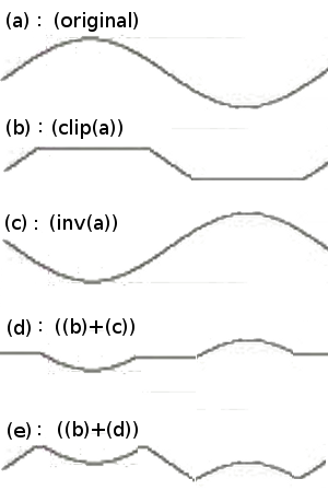
Figure 3. Fold-Back Distortion Process Decomposition
The original signal is shown in the Figure 1 (a), and this original is then clipped at the level of fold-back-level to produce (b). The original signal (a) is also inverted to produce the inverted signal (c). An arbitrary signal (d) is generated by subtracting (b) with (c), and the output (e) is produced by subtracting (b) with (d). Next, we can write the equations as the following:
(e) = (b)+(d)
= (b)+((b)+(c))
= 2(b)+(c)
The final form, 2(b)+(c), means that the output is the sum of the amplified clipped signal and the inverted signal, and the amplification factor of the clipped signal is 2. The schematic diagram of the circuit implementing this process is shown in the Figure 4. The circuit consists of 5 operational amplifiers serving five different functions.
Figure 4. Hamuro Fold-Back Distortion Circuit Schematic Diagram
The first op-amp U2A is employed to stabilize the internal ground (which is symbolized by horizontal strips), which is actually a 1/2 supply voltage in relative to the voltage between positive supply voltage and the external ground (which is symbolized by diagonal strips). There is no special requirement for this function, and since the circuit make use only 1/4 of the available op-amps in the U2 integrated circuit (LM324) chip, we might think that it is wasting many resources and to save the space and cost we can actually use other op-amp chip like 741 series or any other cheap op-amp, and it will work. The concept of internal ground is used in this circuit to enable the internal circuitry to be configured as direct DC coupling to avoid the need of capacitor decoupling while maintaining single supply (non symmetric power supply) operation. Please note again that the power supply and external connection (input and output) uses external ground rather than the internals.
The second op-amp U1A is used to provide signal buffering, provide high impedance for the input, and provide low impedance for further processing. A decoupling capacitor C1 is provided to decouple the DC voltage, since there is voltage gap between external and internal grounding system.
The third op-amp U1B provides the amplification function, and this his pre-amplification is needed since the next processing stage, the signal clipping (U1C op-amp), will be done at fixed point of fold-back level. This original signal amplitude manipulation, in a relativity point of view, can provide a way of the fold-back point manipulation in relative to the original signal. The back-to-back capacitors C3 and C4 provide a non-polar capacitor using two cheap electrolytic capacitors, so it is fine if we replace them with a single non-polar capacitor. If the decoupling capacitors C3 and C4 are not used here (by directly connecting VR1 to the op-amp input), then the amplification would be unstable because it will amplify small DC offset (contained in the signal) to saturate the op-amp output (latching to positive or negative/external ground voltage). In the experiment, using a polar, a single electrolytic capacitor for this decoupling function wouldn’t work, since the small leakage when the input signal contains small DC offset in reversed direction will be amplified with extreme gain.
The fourth op-amp U1C provides the signal clipping function, which limit the signal amplitude of the output at a fixed level. The level of this clipping point is determined by the diodes D1…D4. The diodes D1 and D2 limit the positive cycles of the signal, since above their forward bias voltage, the diodes will behave like a very low resistor that lower the gain of the amplifier. In the same way, the D3 and D4 limits the amplitude of the negative cycles.
The fifth op-amp U1D is configured as a summing amplifier, to sum up the clipped signal and the original signal. When we look at the clipper (U1C), it shows in addition to clipping the signal, it inverts the signal as well. Before summed up by U1D, it is not important whether the process of inverting is done in the original signal or in the clipped signal. What is important is that both signals must have opposite polarity each other. The gain factor (of two) for the clipped signal (in relative to the original signal) is provided by providing double 47k resistor (R5 and R6) as the summing resistors in the original signal path, attenuating the original signal to the half of the clipped signal. The result of the analog version of this effect can be watched in the Youtube video channel below.
Possible Improvement for Hardware Version
Both videos of software and hardware version are recorded using old pocket camera, and it has low quality audio. Although it is not very clear, we can still hear that the “phew” sound in the digital version has stronger effect. It might be because the digital processing produce very sharp clip, a sudden fold-backing actually, since the signal will be suddenly flipped back right after the original amplitude cross the fold-back point. The hardware version can be possibly improved by selecting sharper switching diodes (on-off transition curve of bias voltage in the diode or break-down voltage if we use Zener diodes).