Writing Simple Software Serial Function in Arduino
Introduction: Hardware Serial Vs Software Serial
Arduino hardware and software development platform provides both hardware serial and software serial communication libraries. Hardware serial communication uses the microcontroller’s internal serial interface hardware that manage the digital signaling on its pin, even computing the parity bit for data transmission or for checking the received data if required (configured), so the CPU can be employed to do other things while the data is being transmitted or received. Software serial provide the same function by doing all the necessary actions in the software, executed by the CPU itself. Unfortunately, both Arduino’s native hardware and software serial takes many bytes of the program space. It consumes significant space if we code for ATMEGA8 or ATTINY microcontroller for small low cost project, such as in Arduino project for soldering station controller using ATMEGA8.
Minimum Serial Communication Requirement and Its Application
Serial communication can be implemented as a very simple program by implementing only very basic serial communication function. Let’s make a checklist for defining a very simple requirement:
- A fixed low baud rate: 1200 baud per seconds. A low baud rate will be more reliable, especially when working with low cost system such as ATMEGA8 with only internal RC-oscillator (factory-calibrated).
- Data frame: 1 start bit, 8 data bit, and 1 stop bit, no parity. Computing parity bit will add some complexity (so the program space), and we don’t need this as we can do some checking on the higher protocol layer.
- Polling mode only, so we need not to implement a complicated interrupt service routine. No other task can be done by the CPU when transmission or reception is in progress.
- Simplex and half duplex only, so the program should be receive-only, transmit-only, or receive and transmit alternately. This simplicity would avoid the complexity of CPU multitasking, since everything is handled by the CPU when doing the bit-by-bit data transmission or reception.
With such simplicity, we can find many applications in many occasions, such as debugging and monitoring, or setting up a configuration. Here some possible scenarios where it can be applied:
- A debugging tool just to show some program states, error message, or variable monitoring during development. It commonly requires transmit-only, no need for receive-function.
- Some configuration set up might be more convenient to be done through serial communication than through a very simple interface such as up-down button and some LED blinks. Even some configuration set up should be hidden from the user and should be accessible only for factory set-ups, calibration, automated testing, or trouble shooting.
Serial Data Transfer Protocol and How to Implement in The Software
To enable transmitting the data via serial channel, the data bits should be transmitted one-by-one, as a time series of data bits. The data frame format is shown in the figure 1, showing the timing chart to show how the start bit, data bits, and the stop bits should be placed in time.
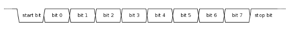
Figure 1. Serial Data Frame
First, when there’s no data, the transmission line (tx-line) should be high (the serial TTL-level standard). Transmitting a data should be done by pulling down the line for 1 baud time period (let’s call it bit time), then pulling it high or low during according to the bit values during bit0 to bit7 bit time. Low means the data bit = 1 and high means the data bit = 0, so the binary data 00000000 means all high during bit0-bit7 bit time, and binary data 11111111 means all low during bit0-bit7 bit time. Receiving the data is the reversal process of the transmission, if a transition from high to ow is detected, then it needs to wait for 1.5 bit time to get the center of bit0 bit time for valid bit reading.
Serial Read Function
Source code 1. shows the serialread() function, which provide the very basic function to handle the serial reading on the receive (RX) pin and its decoding.
[cc language=”cpp”]
#define RXPIN 0
#define TXPIN 1
#define BAUDRATE 1200
#define BITTIME 1000000/BAUDRATE
#define HALFBITTIME 500000/BAUDRATE
char serialread()
{
char rxdata=0;
while(!digitalRead(RXPIN)); //wait until rxline get high if low
while(digitalRead(RXPIN)); //wait until rxline goes low
delayMicroseconds(HALFBITTIME); //wait to get the center of bit time
for(byte i=0;i<8;i++)
{
delayMicroseconds(BITTIME);
rxdata = rxdata | (digitalRead(RXPIN)<<i);
}
delayMicroseconds(HALFBITTIME); //wait till the stop bit time begins
return rxdata;
}
[/cc]
Source Code 1. Serial Read Function
To read a serial data from input line, first we have to make sure the line is high or in the idle state. That’s why the code line 10 wait for high condition if currently low. If already high then the state will be waiting for the start bit, which is indicated by low transition from the high level (line 11). After the start condition is detected, we have to wait for the half of the bit time (line 12) so we would get the center of the start bit before entering the loop for acquiring the data bits (line 13-17). In the loop, what to do is waiting to get the center of the bit time (line 15) and then read the data bit and decode it to place in the right position in the data byte (line 16).
Serial Write Function
The opposite function is serial write, which decodes the input byte into the bits and their timing, getting the right time to write onto the transmit line. The program’s listing is shown Source Code 2, The Serial Write Function.
[cc language=”cpp”]
void serialwrite(char data)
{
digitalWrite(TXPIN,0); //initiate start bit
for(byte i=0;i<8;i++)
{
delayMicroseconds(BITTIME);
digitalWrite(TXPIN,(data>>i)&1);
}
delayMicroseconds(BITTIME);
digitalWrite(TXPIN,1); //write the stop bit
delayMicroseconds(BITTIME);
}
[/cc]
Source Code 2. Serial Write Function
Comparison with The Built-In Arduino Serial
For comparison, the blank setup() and loop() functions without any additional variable declaration takes 314 bytes when compiled for ATMEGA8 in my Arduino development tool. The very basic function to be tested is shown in the Source Code 3 for Arduino’s built in Serial library, and Source Code 4 for out simple serial function.
[cc language=”cpp”]
void setup() {
Serial.begin(1200);
}
// the loop routine runs over and over again forever:
void loop() {
char c;
if(Serial.available())
c = Serial.read();
Serial.write(c);
}
[/cc]
Source Code 3. The Very Basic Application Using Arduino Built-in Serial Library
[cc language=”cpp”]
#define RXPIN 0
#define TXPIN 1
#define BAUDRATE 1200
#define BITTIME 1000000/BAUDRATE
#define HALFBITTIME 500000/BAUDRATE
char serialread()
{
char rxdata=0;
while(!digitalRead(RXPIN)); //wait until rxline get high if low
while(digitalRead(RXPIN)); //wait until rxline goes low
delayMicroseconds(HALFBITTIME); //wait to get the center of bit time
for(byte i=0;i<8;i++)
{
delayMicroseconds(BITTIME);
rxdata = rxdata | (digitalRead(RXPIN)<<i);
}
delayMicroseconds(HALFBITTIME); //wait till the stop bit time begins
return rxdata;
}
void serialwrite(char data)
{
digitalWrite(TXPIN,0); //initiate start bit
for(byte i=0;i<8;i++)
{
delayMicroseconds(BITTIME);
digitalWrite(TXPIN,(data>>i)&1);
}
delayMicroseconds(BITTIME);
digitalWrite(TXPIN,1); //write the stop bit
delayMicroseconds(BITTIME);
}
// the setup routine runs once when you press reset:
void setup() {
//initialize the TX/RX pin
pinMode(RXPIN,INPUT_PULLUP);
pinMode(TXPIN,OUTPUT);
}
// the loop routine runs over and over again forever:
void loop() {
char c = serialread();
serialwrite(c);
}
[/cc]
Source Code 4. Very Basic Application Using Simple Software Serial Function
From the compiled codes, the simple software serial uses only 938 bytes, so it adds only 624 bytes to the empty setup() and loop() 314 while Arduino built-in serial uses 1452, or it adds 1138 bytes. So it saves 514 bytes if we use our small software serial codes, and it would be useful when we code for small microcontroller like ATMEGA8 or even ATTINY series.
More Practical Codes: Read Line and Write Line Functions
In real application, reading only one character migh be useless, and we need more complex task to read and write some string. Here we can implement the writeln() and readln() functions to ease the development, the source codes is shown in Source Code 5.
[cc language=”cpp”]
void writeln(char* buffer, int length)
{
int pos=0;
while(pos<length)
{
if(buffer[pos]==0)
break;
serialwrite(buffer[pos]);
pos++;
}
}
void readln(char* buffer, int length)
{
int pos = 0;
char c;
while(1)
{
c = serialread();
if(c==13) //enter or carriage return
{
buffer[pos]=0; //add null termination
break;
}
buffer[pos] = c;
pos++;
if(pos>=length) pos = 0; //overflow, circle to the start
}
}
[/cc]
Source Code 5. Serial Read Line and Write Line Functions
The readln function accepts char buffer pointer and the buffer length as the parameters. To be simple, it won’t stop reading after the buffer is full, but it would circle to the first position and lets the invalid data to be handled by the application. When it detects an “enter” or “carriage return” character code it then return or exit from the function, regardless the buffer has been full or not. This means that the serial command string length can be variable between zero and the buffer length. The writeln function will print the buffer content until the last character or until a null termination character is detected in the buffer at any position. So the length of the standard c-string stored in the buffer can be variable (up to the buffer length). The practical example of using this functions is shown in the Source Code 6.
[cc language=”cpp”]
char serialbuffer[20];
// the setup routine runs once when you press reset:
void setup() {
//initialize the TX/RX pin
pinMode(RXPIN,INPUT_PULLUP);
pinMode(TXPIN,OUTPUT);
}
// the loop routine runs over and over again forever:
void loop() {
readln(serialbuffer,20);
writeln(serialbuffer,20);
}
[/cc]
Source Code 6. Practical Example Using Serial Read Line and Write Line Functions
With those readln and writeln functions, I have successfully implemented the configuration mode for HM-936D soldering station controller project with ATMEGA8 microcontroller, with custom string to integer conversion routine since the whole system uses fix point (integer) math. While avoiding writing the codes in assembly, this functions save a lot of program spaces to implement many routines for sensor reading, calibration menu, signal processing, software mode pwm, PID (proportional-integral-differential) control, Celcius/Fahrenheit conversion, and segment display multiplexing.