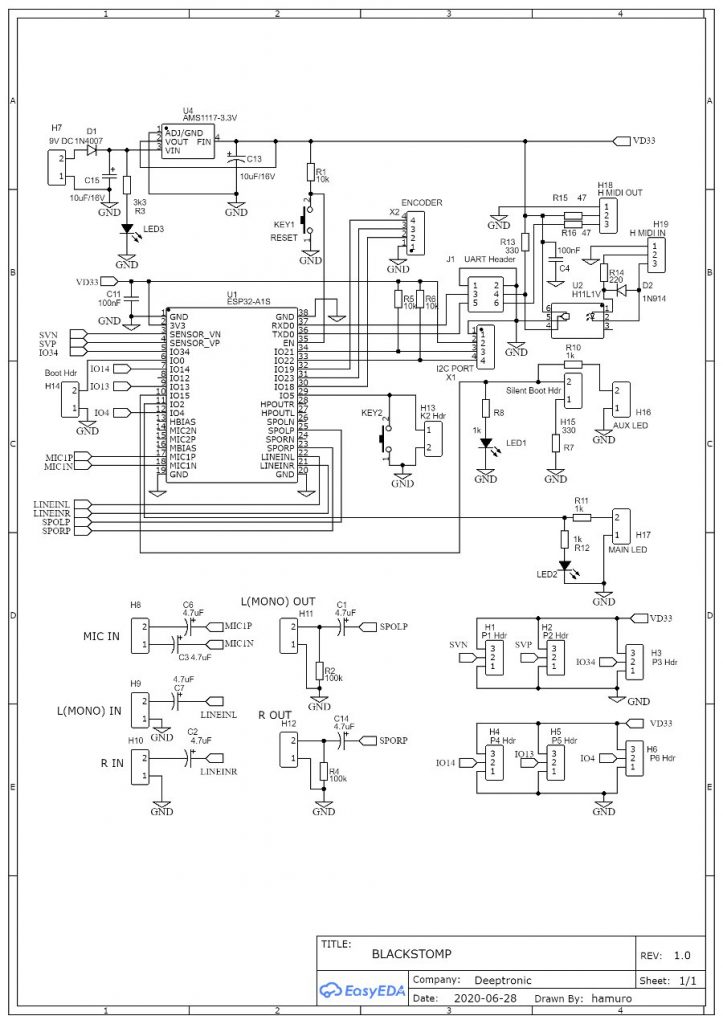
I.1. Schematic Diagram
The schematic diagram of the standard Blackstomp board is shown in the Figure 1. The circuit of the standard board is optimized (and compromised) between development and production usage.
Bill of Materials
| ITEM | COMPONENT | REF | QUANTITY |
| 1 | 100k | R2,R4 | 2 |
| 2 | 10k | R1,R5,R6 | 3 |
| 3 | 330 | R7,R13 | 2 |
| 4 | 1k | R8,R11,R12,R3,R10 | 5 |
| 5 | 220 | R14 | 1 |
| 6 | 47 | R15,R16 | 2 |
| 7 | 10uF/16V TANT | C15,C13 | 2 |
| 8 | 4.7uF/16V ELCAP | C14,C1,C6,C7,C2,C3 | 6 |
| 9 | 100nF MLCC | C11,C4 | 2 |
| 10 | 1N4007 | D1 | 1 |
| 11 | 1N4148 | D2 | 1 |
| 12 | RED LED | LED1,LED2,LED3 | 3 |
| 13 | H11L1V | U2 | 1 |
| 14 | SMD Tactile Switch | KEY1,KEY2 | 2 |
| 15 | AMS1117-3.3V | U4 | 1 |
| 16 | ESP32-A1S | U1 | 1 |
| 17 | Male Header 1×2 | H7-H17 | 11 |
| 18 | Male Header 2×3 | J1 | 1 |
| 19 | Male Header 1×8 | H20 | 1 |
| 20 | Male Header 1×4 | X1,X2 | 2 |
| 21 | Male Header 1×3 | H1,H2,H3,H4,H5,H6,H18,H19 | 8 |