I.2. Reset and Booting
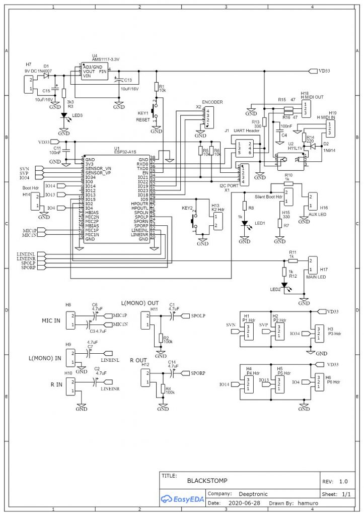
Reset Button. KEY1 is the on-board reset button, is especially useful in development, testing, or reparation service. In a final product the on-board reset button should be inaccessible inside the enclosure, so any reset action (if needed) should be done by power cycling (unplugging and re-plugging the DC power input).
Silent Boot. H15 is a header connector for silent boot jumper, which should be always shorted (by inserting a shorting jumper) most of the time (unless we need to monitor the boot debugging message at power-on). Every time the power is turned on, the system will check if this pin is kept low (shorted to ground through a 330R resistor) or not. If not kept low, the system will send the booting message to the UART port and this might cause erroneous response of MIDI-connected devices during power-on booting.
Boot-Loading. H14 is a boot-loading jumper header, which trigger the UART boot-loading process if IO0 pin is kept low (by shorting the H14 connector pins) during startup (after power-on or reset). To program a new firmware, just short the booting jumper header pins and press the reset button or unplug-replug the DC power input, then you can run the flasher program on your PC to transfer the firmware through UART/J1 port (using USB-to-Serial-TTL cable).