I.9. Recommended Development-Mode Pedal Wiring
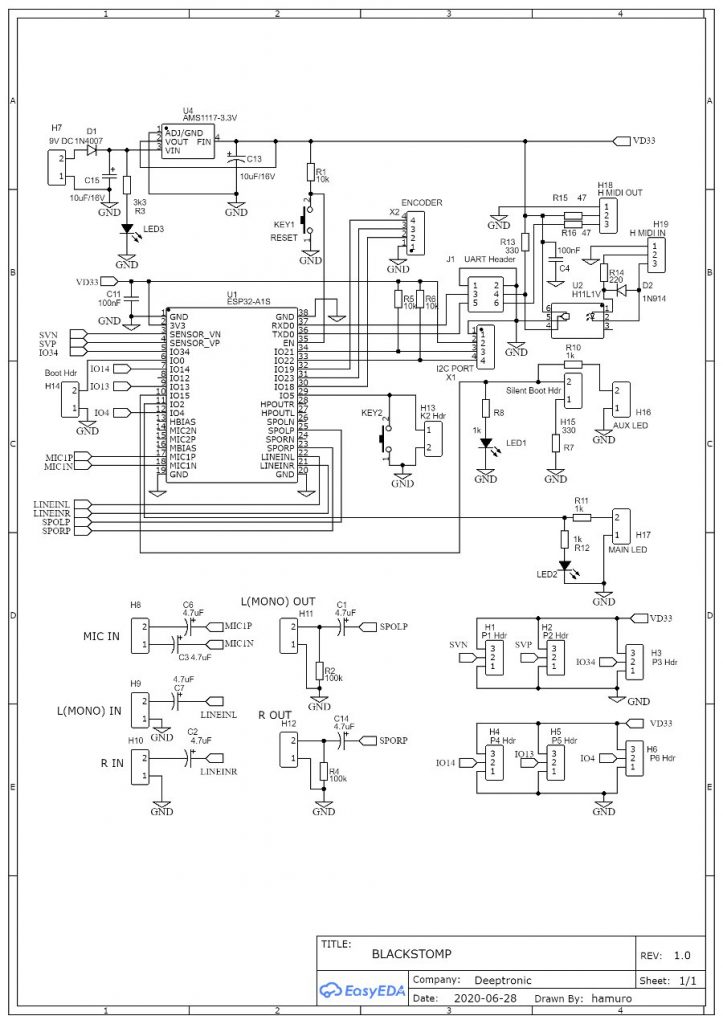

The recommended wiring for development-mode pedal is shown in the Figure 6. The schematic diagram shows the wiring of the off-board components. Here is the bill of (off-board) materials:
| NUM | PART NAME | QTY. | Connection Reference | Connection Description |
| 1 | DC socket for 9V DC input. | 1 | H7.1 | DC input |
| 2 | SPST (normally open, momentary) foot switch | 2 | H13.2, X2.4 | Main and aux button |
| 3 | Red LED | 3 | R(1K), H16.2, H17.2, | Power, main, and aux LED indicators. |
| 4 | 1K Resistor | 2 | VD33, H2.2 | Power LED and control port current limiter |
| 5 | 330R Resistor | 1 | VD33/H6.3 | EXP.P/CV 3.3V source current limitter |
| 6 | SPDT ON-ON toggle switch | 2 | H14, H7.2 | PROG/RUN switch and ON/OFF switch |
| 7 | DPDT ON-OFF-ON toggle switch | 1 | J1 | UART/MIDI switcher. |
| 8 | TS socket 6.3 mm | 4 | H9, H10, H11, H12 | L/R inputs and outputs |
| 9 | TRS socket 6.3 mm | 1 | R(1K), R(330), POT | EXP.P/CV IN. |
| 10 | TRS socket 3.5 mm | 7 | H8, H18, H19, J1, X1, VD33, X2 | MIC, MIDI, UART, I2C, DC OUT, ENC. IN |
| 11 | Potentiometer B10K | 6 | H1, H2, H3, H4, H5, H6 | Control Knobs |
Power-ON LED indicator is very important for development-mode pedal, while it’s not needed for most end products. In an end-product, we can always use the main LED as the CHECK indicator to see if the effect is engaged or not. In contrast, we need a more reliable power indicator to make sure if the power supply is indeed working while debugging the algorithm, including the part that operate the LED indicator.
CTRL 2 potentiometer share the function of analog expression pedal or control voltage (CV) input (CTRL 2/EXP.P/CV). If a TRS jack is plugged into the EXP.P/CV IN socket then the TRS connector will takeover the CTRL 2 potentiometer connection.
Encoder input port. For the most accessible and available part, the port is implemented as 3.5 mm TRS socket and it has only 3 channels and it accommodates only the GND (X2.1), X2.2, and X2.3. The X2.4 input (for the rotary click button) is available on 3.3V port at RING channel, but keep in mind that this input is shared (in parallel) with the second foot switch (the aux button).
PROG/RUN toggle switch determine if the system should run the bootloader (firmware programmer/loader) or run the already programmed firmware when the system starts (after power-on or after reset). At PROG position, every time the power is turned-on or the reset button is pressed then a bootloader program will be started. Starting a bootloader program means that the system will be waiting a stream of firmware’s binary stream on UART port (sent by a PC that runs a flash programmer application) to program the flash storage with new firmware codes. At RUN position, the pedal will run the effect as in normal usage. Switching the PROG/RUN into any position while the pedal is already running has no effect until the pedal restarts.