I.3. Indicator LEDs
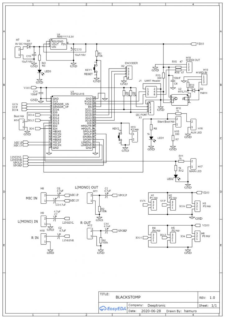
LED1 is the main indicator, and LED2 is the auxiliary indicator. The main and auxiliary labelling is just for reference, as both LEDs have the same capability and we can program them independently. LED1 and LED2 are the on-board LEDs, and the panel- or enclosure-mounted indicator LEDs should be connected off-board through the header connector H16 and H17. For development mode, it is recommended to install all the on-board indicators. It is possible to add more LED indicators through I2C port (X1) using I2C LED driver chip/controller.