I.8. UART (Serial TTL) and MIDI Port
The universal asynchronous receiver transmitter (UART) is primarily used to write the program into the flash memory, but it also handles other functions. The same port is also used for debug monitoring and MIDI communication. The J1 jumper connector is provided to enable alternate use of UART and MIDI interface:
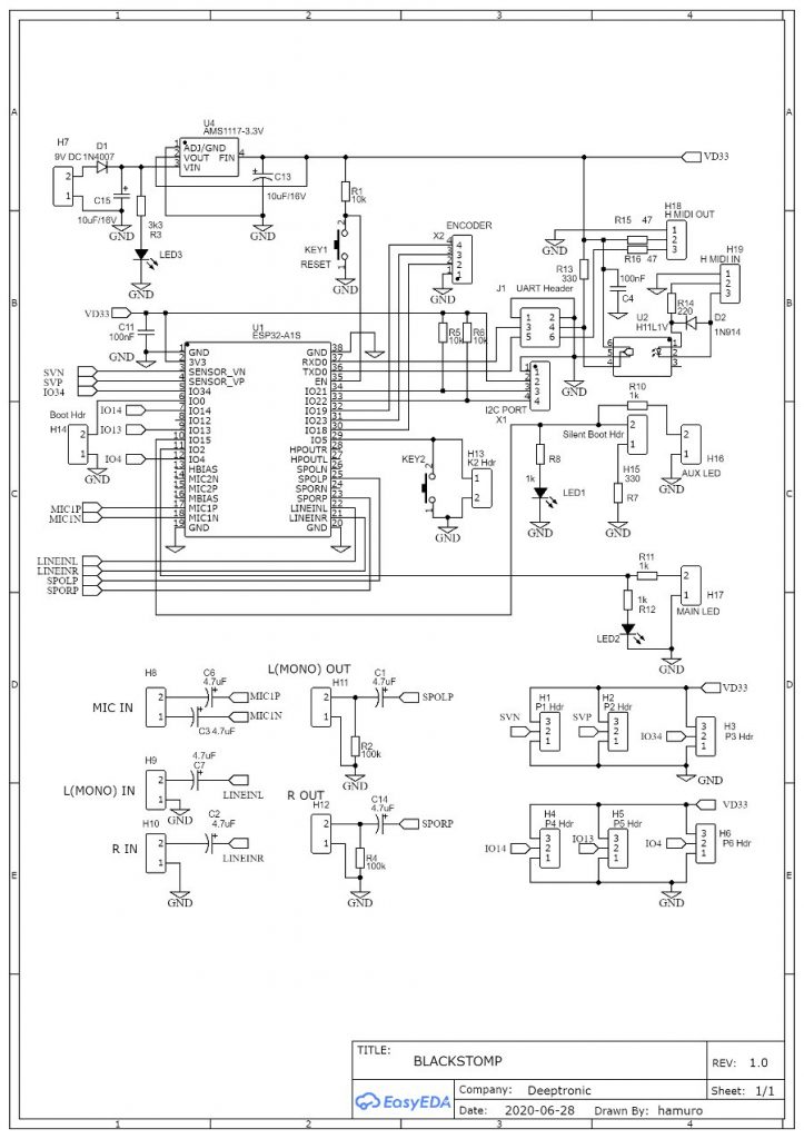
- To use an UART/Serial interface, connect the serial pinout of the J1 header, i.e. J1.1 (GND), J1.3 (RX), and J1.5 (TX) to the serial cable or connector.
- To use the MIDI port, insert two jumpers into the J1 header to short the pins J1.3-J1.4 and J1.5-J1.6, and now the MIDI ports (H18 and H19) is activated.
The alternating use by means of jumper and direct connection to J1 header as described above is recommended for one-time board programming in a mass production, where once after the flash programming is done then we can insert the jumpers to enable the MIDI port almost permanently. In development process, where we frequently need to switch the function between UART and MIDI back and forth, a mode switcher connection using ON-OFF-ON DPDT is recommended (see section I.9)