HM936D-AM8 Digital Soldering Station Controller Chip – User and Developer Manual
Soldering Station Controller Chip
Product Description
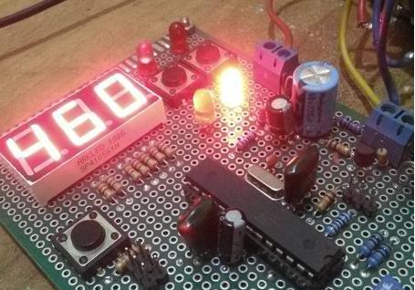
HMC936D-AM8 is a controller chip for HM-936D digital soldering station controller board. The controller is implemented using ATMEGA8 microcontroller, programmed with lock protection to disable the chip for being read or modified. It runs on 8MHz internal factory calibrated RC clock, so there is no need to provide XTAL and its related capacitors. The operational menu, custom sensor calibration initialization, and control parameter can be customized for general controller supporting many heater cartridges with various sensor types, as well as for special controller (of your own brand) to work specifically with your supplied cartridge only.
WARNING!!! Avoid using ICSP port when using this controller chip since the chip might be accidentally erased, and the function of this chip could’t be restored after erasure. Use only the serial port (RX/TX) for configuring this controller.
End Product Features
- Convenient user interface in both Celsius and Fahrenheit modes
- Control range 100 ºC – 450 ºC control range (in Celsius mode) or 215 ºF – 840 ºF (Fahrenheit mode)
- Setpoint control resolution 1 ºC (Celsius mode) or 5 ºF (Fahrenheit mode)
- Supports heater cartridges with different sensor types (RTD , thermocouple, or even unknown sensor type)
- Easy calibration procedure
Development/Mass-Production Features
- Configurable for both common anode or common cathode type of seven segment display, getting more options for the better price and availability.
- Configurable seven segment remapping for the display, this allows flexible PCB design with various seven segment display pin configuration from various vendors.
- Configurable default setting (the first time when the product is delivered to the customer) for Celsius/Fahrenheit mode, easier for targeting different customer preferences around the world.
- Configurable number of supported sensor types and its calibration initialization parameters, so you can set the system to work with all sensor types (RTD, thermocouple, or general/unknown type), or you can configure it to work with only specific type of your supplied heater cartridge.
- Configurable control parameters (proportional, integral, and differential gain), so you can tune up the system to get the best performance for the configured sensor types.
End User Operation Manual
This manual should be customized according to your product configuration, for example, if you configure the controller to work only with specific sensor type (of your supplied cartridge) then remove the sensor type SE1 and SE2 from the list of heater cartridge initialization menu.
- Identifying The Station’s User Interface (please complete this section with the layout of your soldering station product)
- Power-on switch: Turn the system on or off.
- Power-on indicator: On means the system is powered (and it should work), off means the system is not powered.
- Display (3 digits Segment Segment), in normal operation it shows the actual temperature of the soldering tip. In set point edit operation it show the edited setpoint (before actually applied). In menu operation, it shows the menu options and the status of operation after one menu is selected.
- Celsius Indicator: Turned-on means the system works in Celsius mode. Blinks means the system is in setpoint edit operation (and the display shows the edited setpoint), continuous-on means the display shows the actual soldering tip temperature.
- Fahrenheit Indicator: Turned-on means the system works in Fahrenheit mode. Blinks means the system is in setpoint edit operation (and the display shows the edited setpoint), continuous-on means the display shows the actual soldering tip temperature.
- Down and Up button: This button is used to change the temperature setpoint in the setpoint edit operation or to select many functions in the menu operation. There are four modes of operation: brief press (press and release in less than 0.5 seconds), long press (press and release between 0.5 – 1 seconds), press-and-hold (press and hold more than 1 seconds), and double press (up + down buttons together).
- Calibration trimmer: This trimmer potentiometer is used to adjust the sensor amplifier gain for calibration
- RTD/Thermocouple selector switch or jumper: This selector/jumper is provided to select proper gain range and current biasing for the sensor.
- Normal Operation
- When the system is first powered (turned-on), the sytem will load the saved temperature setpoint and start controlling the soldering iron. In parallel with the controlling action start, the display will show the temperature setpoint for 2 seconds, and the Celsius or Fahrenheit mode indicator will blink to indicate that the system is temporarily in setpoint edit mode. If there is no button press within this 2 seconds period then the indicator will stop blinking, indicating that the sistem enters the normal mode and now the display shows the actual iron temperature.
- Setpoint Edit Operation
- From normal operation condition (the display is showing the actual temperature), pressing the up or down button will enter the setpoint edit mode (no matter it is a brief press, long press, or press and hold), and the Celsius/Fahrenheit indicator will start blinking to indicate this operation mode. The value of the current temperature setpoint will be copied to the setpoint edit value. This setpoint edit value will be shown in the display during the editing.
- After entering the setpoint edit mode, pressing it again will increment of decrement the temporary setpoint edit value. Brief press (less than 0.5 second) will increment or decrement the setpoint edit value by 1 ºC (Celsius mode) or 5 ºF (Fahrenheit mode). Long press (between 0.5 and 1 seconds) will increment or decrement the setpoint edit by 10 unit (both in Celsius and Fahrenheit modes). Press and hold (more than 1 seconds) will increment or decrement the value in the rate of 10 units per 0.1 seconds (both in Celsius and Fahrenheit modes).
- If there no button press in 2-second periods then the system will switch back to normal operation mode and the F/C mode indicator will stop blinking. The value of the setpoint edit will be checked, and if the value is different from the current setpoint then it will be applied to the setpoint.
- Entering Menu Operation
- Pressing up and down buttons together from normal operation mode (showing actual temperature) will make the display start blinking to indicate the menu operation is started. The menu options will be shown in the display, and you can press the down button to select the item and rotate all of the menu items. Long press (more than 0.5 seconds) of the down button will select and rotate back the items. Selecting and rotating the menu items doesn’t do anything until you execute the menu item by pressing the up button at the selected menu item. If you don’t execute the menu and stop selecting/rotating the menu item within 4 seconds then the system will go back to normal operation mode and nothing is done. Here the list of all menu items:
- C: Activate Celsius mode
- F: Activate Fahrenheit mode
- CA0: Registering the calibration data at temperature point 0 (see the calibration section)
- CA1: Registering the calibration data at temperature point 1 (see the calibration section)
- SE0: Initialize new heater cartridge with sensor type-0 (see calibration section)
- SE1: Initialize new heater cartridge with sensor type-1 (see calibration section)
- SE2: Initialize new heater cartridge with sensor type-2 (see calibration section)
- Pressing up and down buttons together from normal operation mode (showing actual temperature) will make the display start blinking to indicate the menu operation is started. The menu options will be shown in the display, and you can press the down button to select the item and rotate all of the menu items. Long press (more than 0.5 seconds) of the down button will select and rotate back the items. Selecting and rotating the menu items doesn’t do anything until you execute the menu item by pressing the up button at the selected menu item. If you don’t execute the menu and stop selecting/rotating the menu item within 4 seconds then the system will go back to normal operation mode and nothing is done. Here the list of all menu items:
- Activating Celsius Mode
- Enter the menu operation by double-pressing up+down buttons from normal operation
- Select C from the menu option by pressing or long-pressing the down button
- Execute the selected menu item by pressing the up button, if success then the display will show “CCC” blinking message to indicate the Celsius mode has been activated. After the blinking stops then the system will be back to normal operation mode.
- Activating Fahrenheit Mode
- Enter the menu operation by double-pressing up+down buttons from normal operation
- Select F from the menu option by pressing or long-pressing the down button
- Execute the selected menu item by pressing the up button, if success then the display will show “FFF” blinking message to indicate the Fahrenheit mode has been activated. After the blinking stops then the system will be back to normal operation mode.
- Please note that the Fahrenheit mode is provided only for display and setpoint setting convenience, and the real values will be internally recorded and handled in Celsius unit by the controller. This limitation might produce some numerical error during conversion since the controller employs fix point math for the computation.
- Calibration
- The soldering station should be calibrated every time the soldering iron unit or its heater cartridge is replaced with the new one. In turned-off condition, set the sensor type selector or jumper properly according to the sensor type of the heater cartridge, unplug the soldering iron unit.
- Without the soldering unit installed, turn-on the station, never mind about the displayed temperature in the seven segment display. Check the Celsius mode indicator, if not active then activate it (refer to section 5). This calibration method should be done in Celsius mode for proper setpoint control since the system is internally works in Celsius mode, and the fix-point computation might introduce some numeric error in Fahrenheit mode.
- Enter the menu operation and select SE0, SE1, or SE2 depending on your sensor type. SE0 for thermocouple type sensor, SE1 for RTD type, and SE2 for general or unknown type. After selected, then execute by pressing the up button, if succeed then a blinking “ACC” message will be displayed as acceptance indication. After stop blinking, the system will enter the normal mode and you can continue the next calibration step
- Edit the setpoint to a high temperature point, 400-450 ºC is recommended. Lower temperature point can be used but it might produce greater error in the higher temperature zone between this point and the maximum controllable temperature point (450 ºC).
- Plug the soldering unit, let the system try to regulate the temperature, and start measuring the soldering tip using a calibrated thermometer. Fast response thermometer is recommended for easier calibration process.
- Adjust the calibration trimmer potentiometer by a screwdriver until the station stabilize the soldering tip at the correct temperature (as shown by the thermometer).
- After the temperature is correct and stable then enter the menu operation and execute CA1 menu item to record this first calibration point data. A blinking “ACC” message will be displayed if CA1 menu is successfully executed.
- Edit the temperature setpoint to 100 ºC and measure the soldering tip temperature. The system will control the iron and stabilize the temperature with some error. By looking at the error amount, now correct the error by adjusting the setpoint (up or down button) until the thermometer show a correct 100 ºC. At this step, the setpoint edit should be able to decrease the setpoint below 100 ºC (down to zero) to achieve the correct reading if necessary.
- After the thermometer shows a stabilized soldering tip temperature at 100 ºC, then enter the menu operation mode and execute CA0 menu item, and blinking “ACC” message is displayed as a success indication. Now the second temperature point data has been recorded, the conversion parameter has been calibrated, and the the station is ready to use.
Development/Mass-Production Manual
HM936D-AM8 digital soldering station controller is designed to enable easy configuration for your custom product. This configuration can be accessed through the serial port of HM936D controller board during development, testing, or final setup in your production cycle.
- Controller’s System Overview
- The block diagram below shows the functional organization of the controller design. The sensor reading is done in every 10 milliseconds to get 100 samples per second, filtered (by simple averaging) and down-sampled to 10 samples per second, synchronized with the PID (proportional-integral-differential) controller. For user convenience, the actual temperature for the display is further down-sampled to 1 sample per second.
- Entering Seven Segment Display Testing Mode
- A common anode display test will be entered if the station is powered-on while the up-button is being pressed and held. The Celsius mode indicator will blink to indicate that this mode is running, and now the button can be released and this mode won’t be exit until get powered off. If the installed display type is common anode then it will show a blinking segment pattern with the default remapping (section 3). The default display of HM936D board uses common anode type, if the employed display is common cathode then it will be blank, and the proper display type configuration should be set by entering configuration mode (section 4).
- A common cathode display test will be entered if the station is powered-on while the down-button is being pressed and held. The Fahrenheit mode indicator will blink to indicate that this mode is running, and now the button can be released and this mode won’t be exit until get powered off. If the installed display type is common cathode then it will show a blinking segment pattern with the default remapping (section 3). The default display of HM936D board uses common anode type, if the employed display is common anode then it will be blank, and the proper display type configuration should be set by entering configuration mode (section 4).
- Seven Segment Remapping
- Each segment in a seven segment display is addressed as a, b, c, d, e, f, and g segments, as shown in the figure.
 When a seven segment display test mode is entered (section 2), the default mapping will be shown by flashing each segment sequentially from a, b, c, d, e, f, and g and then repeated indefinitely.
- The first segment will be flashed in longer duration to indicate the first segment, the following 6 segments will be flashed shorter, and then repeat from the first segment.
- The wiring between microcontroller pin and the display segment shown in the schematic diagram uses the default remapping pattern “0,1,2,3,4,5,6” which means that the test will show valid sequence starts from a, b, c, d, e, f, to g segment before recycling back to a. If it doesn’t show valid sequence then the non default remapping pattern should be configured by entering configuration mode (section 4).
- To find the proper remapping pattern for non default display wiring/connection, mark the segment a, b, c, d, e, f, and g with numbers 0, 1, 2, 3, 4, 5, and 6 respectively. Find the segment with longer flash in the cycle as the first number, next in the second, next is the third, and so on. For example, if the cycle start from g (the longer flash), then f, e, d, c, b, and a; then the remapping pattern is “6,5,4,3,2,1,0”.
- Configuration Mode
- Entering the configuration mode
- A configuration mode will be entered if the station is powered-on while being double-pressed (up+down button being pressed together) and held. The power indicator will be turned-on, while the seven segment and the F/C mode indicator will stay off. The serial interface will send “HM-936D CONFIG” string followed by line break “\n” and carriage return “\r” at fixed 1200 baud/s, in the format of 1 start bit, 8 data bit, 1 stop bit, and no parity; so connect any serial terminal to the HM-936D board with this setting before entering the configuration mode. Make sure the signal level is 5V TTL standard (not RS232 level), use RS232 to TTL or USB to serial TTL converter (such as FTDI chip or compatibles) for PC system terminal. After the “HM-936D CONFIG is sent to the terminal, then you can type the supported string commands : “read”, “smap”, “acom”, “celm”, “senc”, “sega”, “seto”, “sedo”, “prop”, “inte”, and “diff” (should be typed without the quotation marks in the terminal). Please note that the controller doesn’t echo the received command characters, so for your convenience, you have to set a local echo in your standard terminal setting (Arduino’s serial monitor has already done it by self printing the command and sends it only after an enter key is hit).
- Reading The Current Configuration
- Command format: “read”
- Command example: “read”
- Response format: “all:[seven segment map],[common anode mode],[Celsius mode],[sensor type count],[sensor-0 gain],[sensor-0 t-offset],[sensor-0 d-offset],[sensor-1 gain],[sensor-1 t-offset],[sensor-1 d-offset],[sensor-2 gain],[sensor-2 t-offset],[sensor-2 d-offset],[proportional gain],[integral gain],[differential gain]”
- Response example: “all:0123456,1,1,3,04500,030,000,07000,000,320,04500,000,000,01000,00010,02000”
- Note: this command is the only method to confirm what have been saved or modified by any other commands, as the other command response is just echoing the executed command string without any execution status.
- Seven Segment Remapping
- Command format: “smap,[ramapping pattern]”
- Command example: “smap,76543210”, “smap,0456123”
- Response: “smap”
- Note: Default HM-936D controller board with the default display type should use the default remapping pattern “0,1,2,3,4,5,6” (original map), valid pattern for non-default seven segment wiring can be found from bye testing procedure (section 2, 3)
- Anode Common Mode
- Command format: “acom,[mode]”
- Command example: “acom,1”, “acom,0”
- Response: “acom”
- Note: mode = 1 for common anode type(default) and mode = 0 for common cathode type
- Celsius Mode
- Command format: “celm,[mode]”
- Command example: “celm,1”, “celm,0”
- Response: “celm”
- Note: mode = 1 for Celsius mode and mode = 0 for Fahrenheit mode
- Sensor Type Count
- Command format: “senc,[sensor type count]”
- Command example: “senc,1”, “senc,2”, “senc,3”
- Response: “senc”
- Note: valid values for sensor type count are 1,2, or 3
- Sensor Gain Initialization
- Command format: “sega,[sensor type number],[gain]”
- Command example: “sega,0,04500”, “sega,1,07000”, “sega,2,05000”
- Response: “sega”
- Note: sensor type number is associated with SE0, SE1, and SE2 in the menu operation, and the gain value should be coded in 5 digits by leading zeros if needed. This value ranges from 00000 to 10000 representing 0.0 to 1.0 gain range in fix point math.
- Sensor T-offset Initialization
- Command format: “seto,[sensor type number],[offset]”
- Command example: “seto,0,030”, “sega,1,000”, “sega,2,000”
- Response: “seto”
- Note: sensor type number is associated with SE0, SE1, and SE2 in the menu operation, and the offsetvalue should be coded in 3 digits by leading zeros if needed. This value ranges from 000 to 999 representing 0 – 999 ºC of temperature offset initialization.
- Sensor D-offset Initialization
- Command format: “sedo,[sensor type number],[offset]”
- Command example: “seto,0,000”, “sega,1,312”, “sega,2,015”
- Response: “sedo”
- Note: sensor type number is associated with SE0, SE1, and SE2 in the menu operation, and the offset value should be coded in 3 digits by leading zeros if needed. This value ranges from 000 to 999 representing 0 – 999 value of the internal digital reading of the A/D converter at T-offset temperature.
- Proportional Gain Setting
- Command format: “prop,[gain]”
- Command example: “prop,01000”, “prop,00500”
- Response: “prop”
- Note: gain value should be coded in 5 digits by leading zeros if needed. This value ranges from 000 to 32767 representing 0.0 – 3.2767 proportional gain value for the PID controller (section 5).
- Integral Gain Setting
- Command format: “inte,[gain]”
- Command example: “inte,00010”, “inte,00015”
- Response: “inte”
- Note: gain value should be coded in 5 digits by leading zeros if needed. This value ranges from 000 to 32767 representing 0.0 – 3.2767 integral gain value for the PID controller (section 5).
- Differential Gain Setting
- Command format: “diff,[gain]”
- Command example: “diff,01000”, “diff,02000”
- Response: “diff”
- Note: gain value should be coded in 5 digits by leading zeros if needed. This value ranges from 000 to 32767 representing 0.0 – 3.2767 differential gain value for the PID controller (section 5).
- Multiple Parameters Setting
- Command format: “mult,[seven segment map],[common anode mode],[Celsius mode],[sensor type count],[sensor-0 gain],[sensor-0 t-offset],[sensor-0 d-offset],[sensor-1 gain],[sensor-1 t-offset],[sensor-1 d-offset],[sensor-2 gain],[sensor-2 t-offset],[sensor-2 d-offset],[proportional gain],[integral gain],[differential gain]”
- Command example: “mult,0123456,1,1,3,04500,030,000,07000,000,320,04500,000,000,01000,00010,02000”
- Response: “mult”
- Note: this command should be confirmed by “read” command (section 4.2) to check whether all parameters have been successfully set.
- Unrecognized Command
- Command format: [any unrecognized command]
- Command response: “ignored”
- Note: a command is identified by the first 4 characters, and any unrecognized command will be ignored safely. If the first 4 characters is identified as a recognized command but the following parameters format is not valid, then the system might save some erroneous values. This error might also be produced by valid command with the valid parameters but the transmission (cable, connector, etc.) is disrupted. That’s why a confirmation by “read” command is always recommended after sending any other commands.
- Entering the configuration mode
- Control Parameters Tuning
- The proportional-integral-differential controller is implemented as depicted in the block diagram below:
- All the computation is actually done in fix point (integer) math, and the shown parameters are the equivalent floating point value for easy interpretation.
- The proportional gain, integral gain, and the differential gain has default values of 0.1, 0.0001, and 2.0 respectively. These parameters are configurable by “prop”, “inte”, “diff”, and “mult” commands; and the parameters for these commands should be coded by integer value by multiplying the corresponding gain value by 10,000; and it should be written in 5 digits number by adding some leading zeros if needed, resulting in 01000, 00010, and 02000 default p-i-d command’s parameters. These default values should works for most heater with different heating element and sensor type, but if you want the station to use only a specific heater cartridge (of your own product for example) then you can optimize the control parameters by trial and error for the best control performance.
- Keep in mind that the sensor reading resolution is only about 0.5 to 1.0 ºC depending on the sensor’s offset (the reading at 0ºC) which is not null-ed in the hardware before conversion, so it’s safe to assume that the sensor reading is only 1.0 ºC in resolution. As the result, the differential error wouldn’t be detected if the temperature change in the consecutive sampling (0.1 s) is less that 1 ºC.
- Quick Configuration Method for Mass-Production
- For mass-production, configuring many station units can be done around the final testing. A simple computer program can be written to continuously send a”read”, checking the response, and sending the “mult” command if the response show different configuration and an indication that the plugged unit is not yet configured. The algorithm of the automated (continuous) testing-and-configuring can be defined as the following:
- Send a “read” command
- Check the response
- If the response show that all parameters are matched with your custom default factory configuration then generate a “done” indication (something like beep or whatever convenient) and go back to step 1
- Generate a “configuring in progress” indication (something like beep or whatever convenient) and send a “mult” command along with the parameters of your custom default factory configuration.
- Go back to step 1
- After the automated configuration terminal is running, now we can configure many station units quickly:
- Pick a new station and connect its serial port to the terminal
- Double press the up+down button and power-on the station
- Wait for a “done” indication, if it gets “done” then unplug the serial port and power-off the station, and go back to step 1 (for other new station)
- For mass-production, configuring many station units can be done around the final testing. A simple computer program can be written to continuously send a”read”, checking the response, and sending the “mult” command if the response show different configuration and an indication that the plugged unit is not yet configured. The algorithm of the automated (continuous) testing-and-configuring can be defined as the following: