Far Field Noise Cancelling Microphone Pre-Amp Employs Standard Op-Amp
Figure 1. Noise Cancelling Microphones Position
The microphone pre-amplifier circuit described here make the microphone sensitive to a sound come from very close source, and insensitive to any sound coming from far sources. This works even when the far sound is very loud. The main application of this circuit is in telecommunication system like in mobile phones, where the microphone should pick a clear speech even the environment is very noisy like in a night club, airport, train station, or in a rock music performance stage. Although it is applied mainly in telecommunication system, we can use this circuit in other area as well, like in speech amplification in public address or in small meeting room. In such situation, sometimes we have a problem that we can increase the volume of the amplification because feedback is running out of control with loudspeaker-microphone position limitation.
Far Field Noise Cancellation: How It Works
When a sound wave travel through a space, the amplitude is attenuated proportionally with the power of 3 of its distance. When two microphone are closely positioned, we can observe that far sound source will have relatively same distances with both microphones, will have relatively big difference in distance between the first and the second microphone. The two microphones should have identical characteristic to get the best result. When the sound comes from far away, both microphone should produce a same waveform with the same amplitude. This two identical signal is then subtracted to eliminate the far source signal. When applied to a close sound source, the waveform should be identical but with very different amplitude, so the subtraction of the two signal won’t zero the signal but leave a strong signal to be picked.
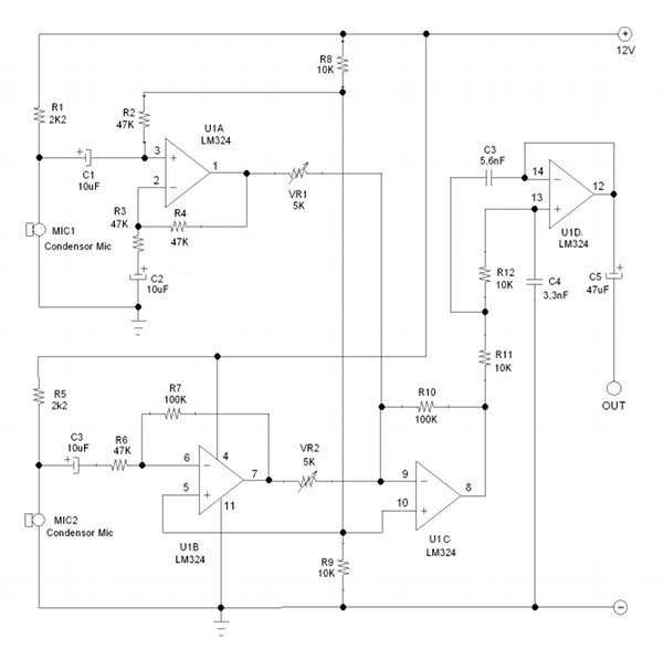
Figure 2. Far Field Noise Cancelling Microphone Pre-Amp Circuit Schematic Diagram
The Electronic Circuit Design and The Schematic Diagram
The circuit design is very simple, it employs a standard operational LM324, which is shown in Figure 2. The first op-amp U1A serves as a non-inverting amplifier, the second op-amp U1B serves an inverting op-amp. The third op-amp U1C serve as a mixer and amplifier which sum up both complementing signals. Finally, the last op-amp U1D serve as a low pass filter to cut the high frequency content of the signal. The high frequency components should be removed since it can be a result of phase-shifted signal of far sound sources coming certain directions. The ideal condition, when the sound is coming from far away sources, are that the signals from the two microphone channels would be identical but with different amplitudes, so it would be zeroed when summed up. The reality, it works ideally only on low frequency, where the wavelength is much longer than the distance of the two microphones. When the wavelength is not much larger than the microphone distance, then the phase-shift will make the signal amplitude (the instantaneous voltage level) not identical to cancel each other at some direction.
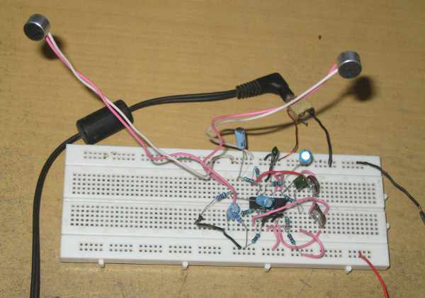
Figure 3. Assembled Far Field Noise Cancelling Microphone Pre-Amp Circuit
Calibration of The Circuit
To calibrate the circuit, VR1 and VR2 is provided to adjust the gain of its respected channel. Just connect the output of this circuit to a big amplifier system (with high power loud speaker), and adjust both variable resistor to produce strong output but minimize the feedback. Adjust the distance of the two microphone around 4-10cm to set the proper sensitive area of the microphone. Make sure the proper positioning between the microphone and the speaker like shown in the Figure 1.