Analog Temperature Controller Circuit for Soldering Station
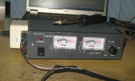
Figure 1. Analog Temperature Controller for Soldering Station
Temperature Controlled Soldering Station
With temperature control, we can take some benefits in soldering: lower cost for electric power, safer operation of soldering critical components from excessive heat, and longer life for the soldering tip. We can save the electricity power consumption up to 50% of the uncontrolled one. A high quality soldering tip, which can be expensive enough, often made from special alloy to make it more adhesive to the soldering tin. This expensive soldering tip often has lower melting point and can be easily eroded if get frequently over heated. Here we present the electronic circuit design for controlling the temperature of a soldering iron. Using analog thermocouple, operational amplifier integrated circuit (IC), and some discrete components, we can easily build a temperature controller which is simple, robust, and cheap.
How The Temperature Controller Works
The controller works by the mechanism of feedback. We measure the actual temperature, compare it with the reference or setting point, and take the action to make the actual temperature approach the desired value (the setting point/reference). We use the simplest form of controller system, a binary controller, which has discrete action: turning the heating filament on or off. When the actual temperature is lower than the set point, then the controller will turn on the filament, and turn it off when it get higher than the set point.
Figure 2. Schematic Diagram of Temperature Controller Circuit for Soldering Station
The Electronic Circuit Design and The Schematic Diagram
The circuit is designed using K-type thermocouple as the sensor and LM324 op-amp as the controller circuitry. The sensor is capable of measuring temperature up-to 400°C, and it should be enough for soldering application. Normal soldering should be set around 300-400°C. The controller circuitry is composed by a sensor amplifier, reference circuit, comparator, and relay circuit. The monitoring of both set point and the actual temperature is done using an analog VU meter. See the schematic diagram of the circuit in the Figure 2.
Can UD be omitted along with vu meters,resistors and diodes ?
Is it just a monitor?
I’ve tried using resistors instead of vu meters for impendance match.
Le diode is sensitive to pot,but doesn’t seem to turn off(itself and relay) with temperature rising,seems like comparator or sensor amp failure.
Regards